Deployment and installation
General instructions
- The device is intended to be installed in restricted access areas and by qualified operators.
- The hight of the installation should be at least 4m.
- Ordinary personnel should not have access to the device (external nor internal).
- Only expert operators should have access to the device for maintenance or calibration purposes.
- This equipment is not suitable for use in locations where children are likely to be present.
Power supply installation
The device works with a 100-240 VAC input. The next image shows how the installation must be done with the given power supply wire.
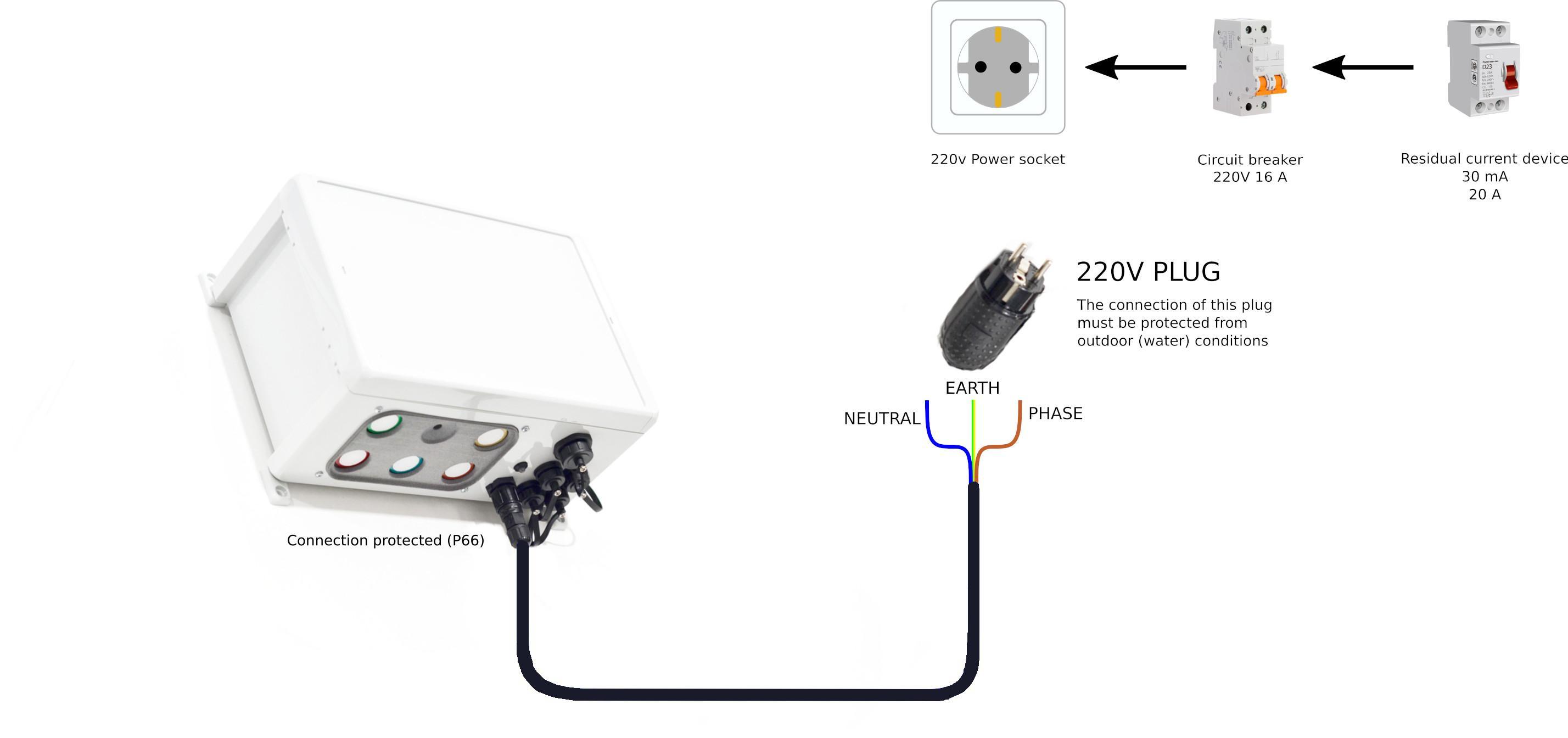
Regarding outdoors installation, please keep in mind proper protection should be applied to the junction of the electrical wires. When terminal strips are used, all wires must be housed properly within a protective enclosure.
The power supply wire provided by Libelium supports earthing connection so it must be connected to the corresponding installation protective earthing conductor.
A Residual Current Device (RCD) protection with rating residual not exceeding 30mA shall be used in the main supply to socket-outlets intended for general use and with a rated current not exceeding 20A.
In addition, a overcurrent protective device (OCPD) provided in the building installation (16A) is required.
Only a qualified personel should perform the installation of electrical connections to the device. A verification of the protective earthing connection of socket-outlet by a skilled person is required.
Device installation
Do not power on the device until all sensors have been plugged. Once the device is powered, the firmware recognizes all sensors correctly installed and they will be marked as active for later measurings.
The device offers 2 installation possibilities: wall installation and lamppost installation. In both cases, the elements necessary to carry out the installation are included (the necessary tools are not included: drill, screwdriver, pliers, etc).
After the first installation, it is recommended to wait up to 24 hours to validate the sensor measurements. By default, a generic A.I. model runs in the Cloud for every Air Quality Station device. However, a "co-location calibration" should be performed in order to obtain the best results.
Lamppost installation
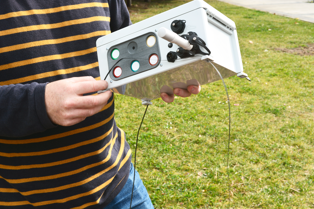
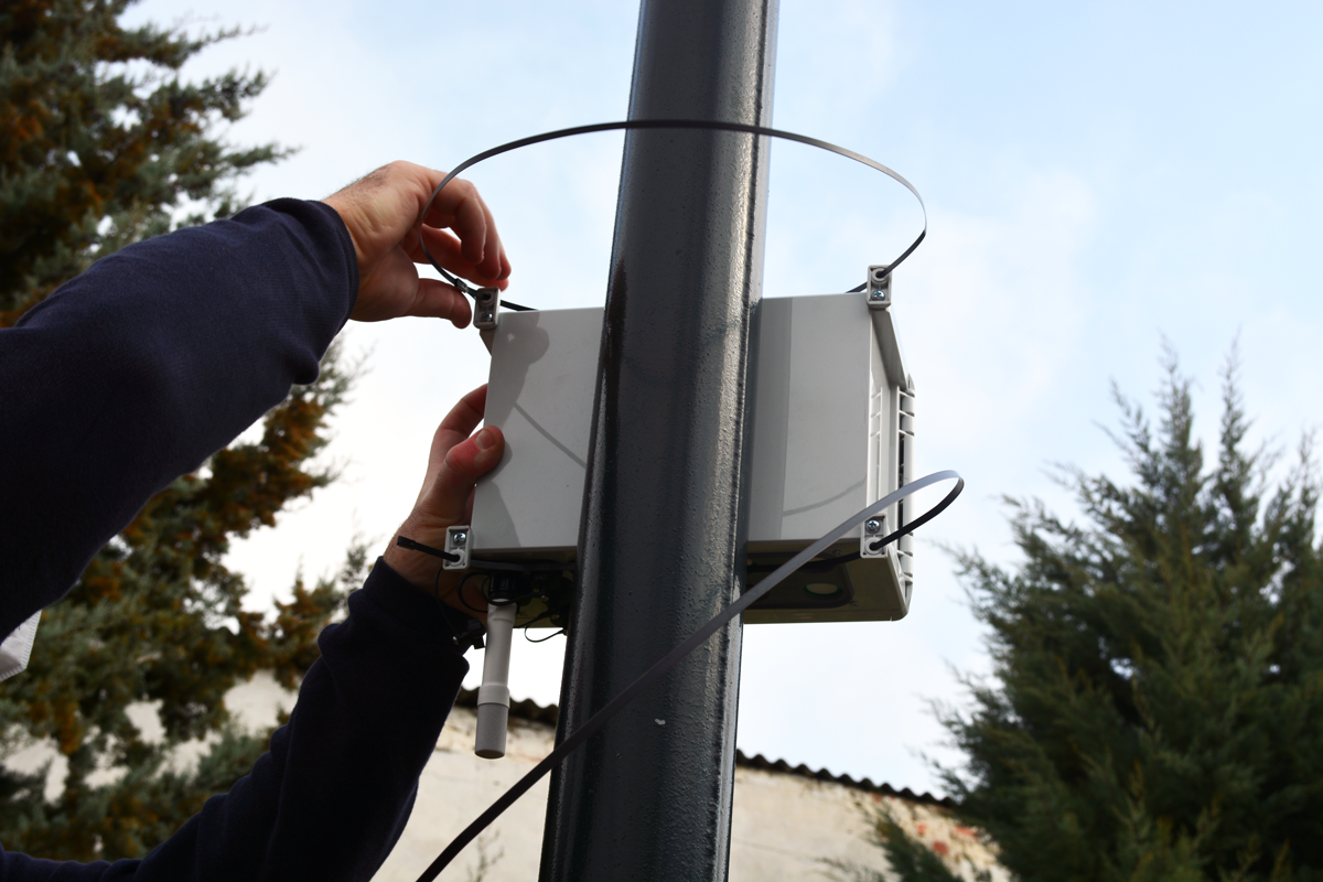
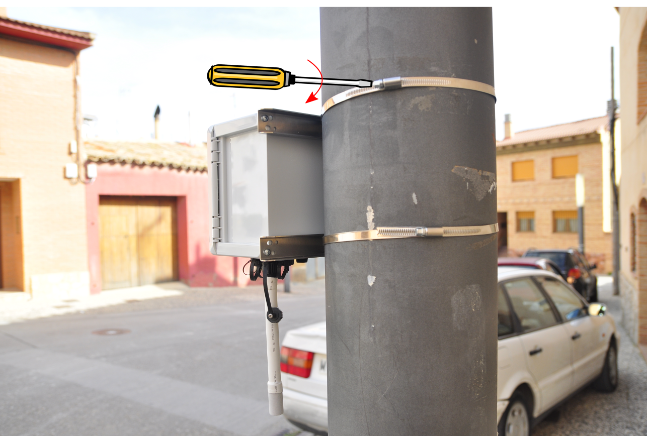
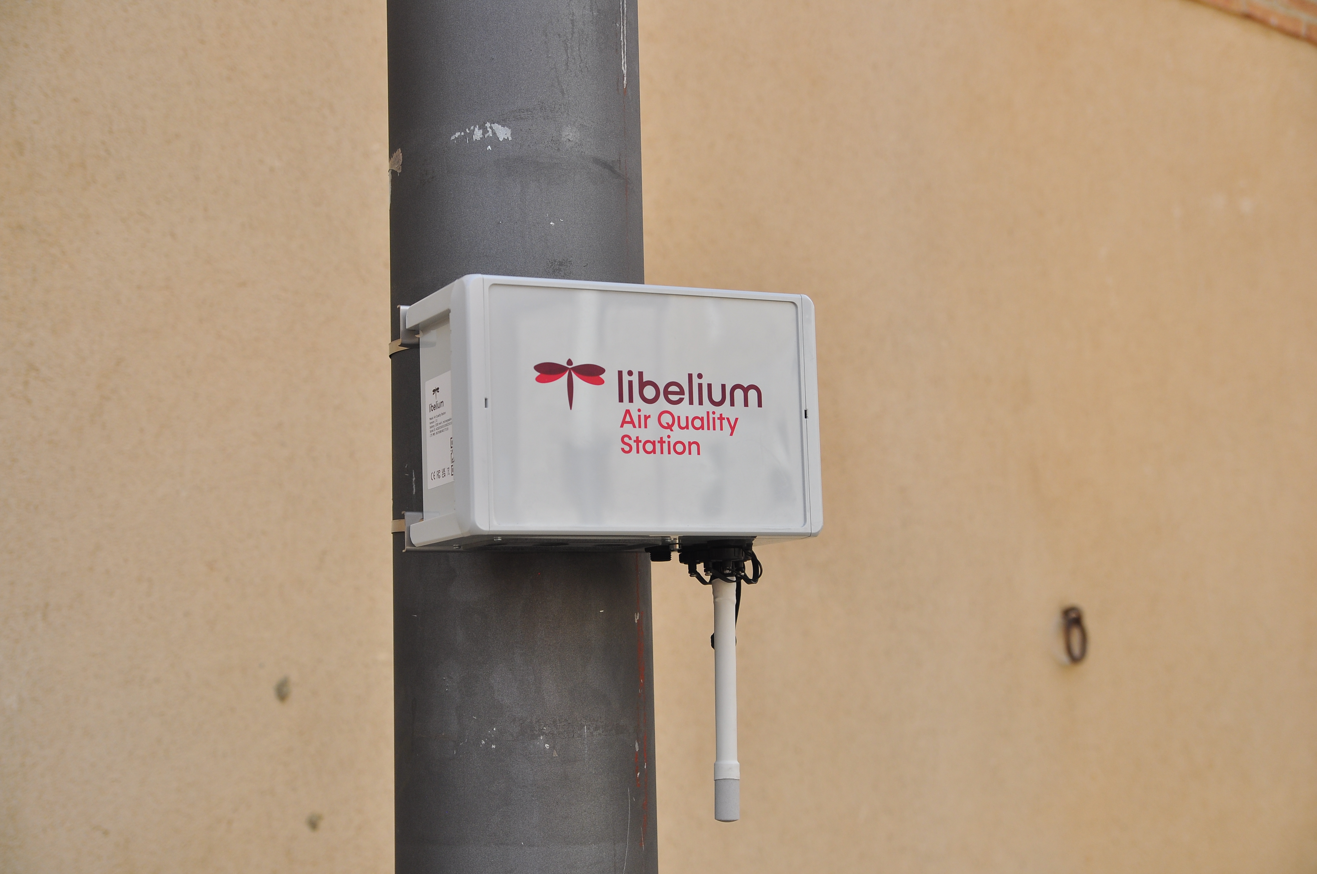
The node can be fixed to a streetlight using the PVC coated stainless steel cable ties provided by Libelium. Always make sure that the enclosure is firmly tied and environmental elements (like wind) do not modify its position.
Place the Air Quality Station device on streetlight tightening firmly the metal cable ties. Be sure that the node remains completely tied to streetlight to avoid it could fall down.
Installation with Lamppost installation kit (optional)
When a robust installation on streetlights or poles is necessary, it is recommended to use the optional streetlight installation kit, valid for poles from 190 to 210 mm.
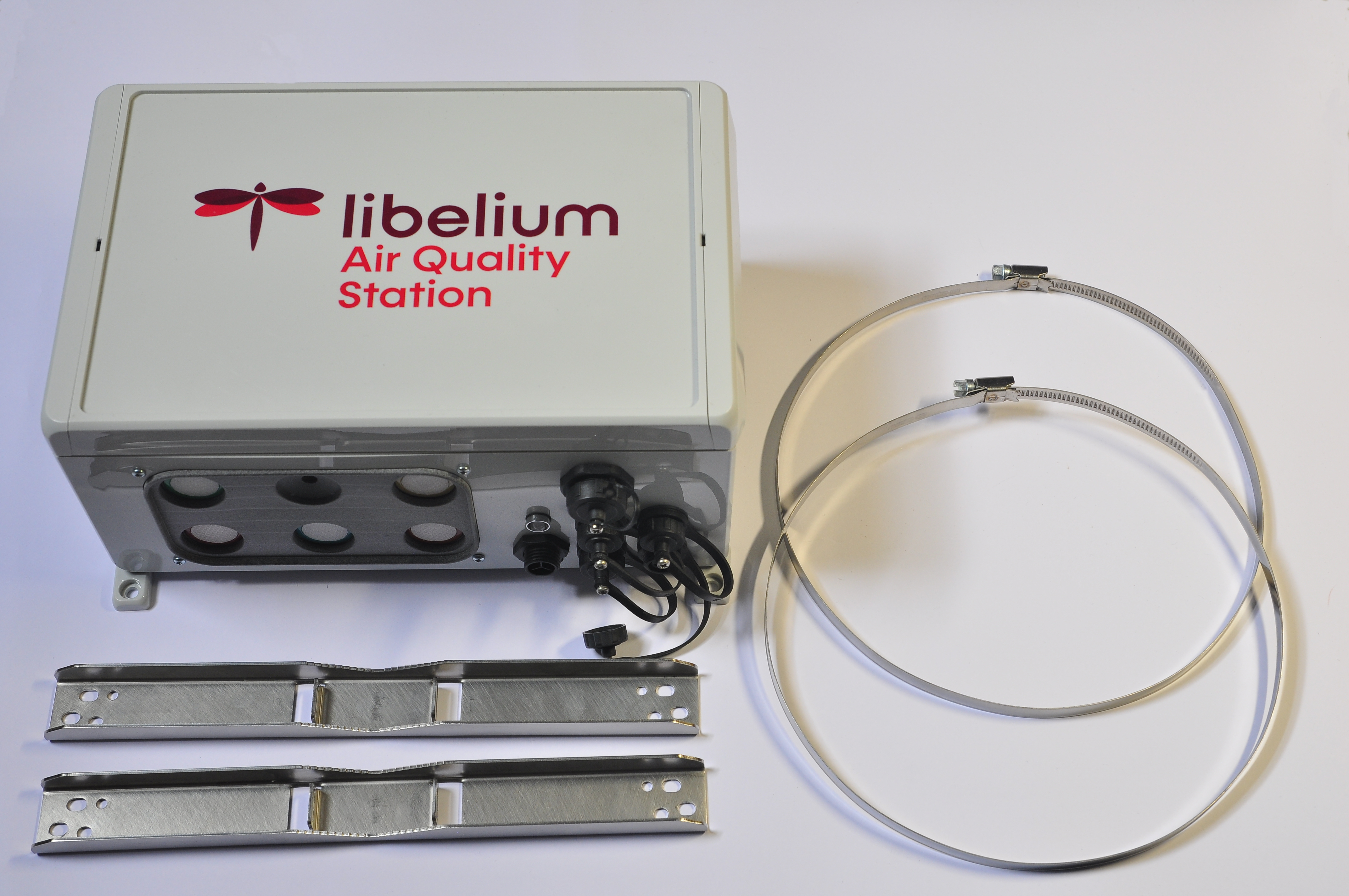
The kit includes two metal clamping pieces and two Worm Drive Hose Clamps. It is installed on the back of the case using the screws that hold the standard fixing pieces.
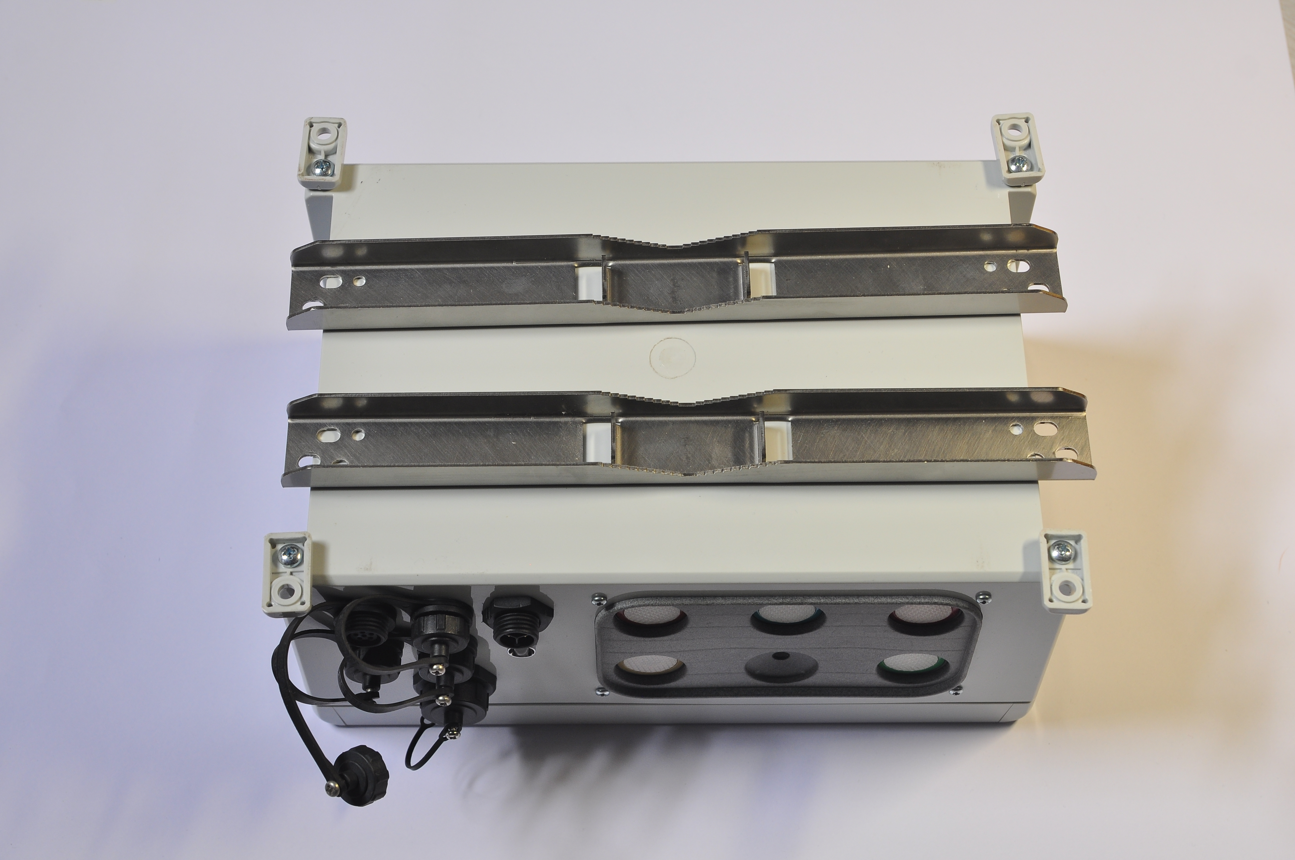
Unscrew the existent screws.
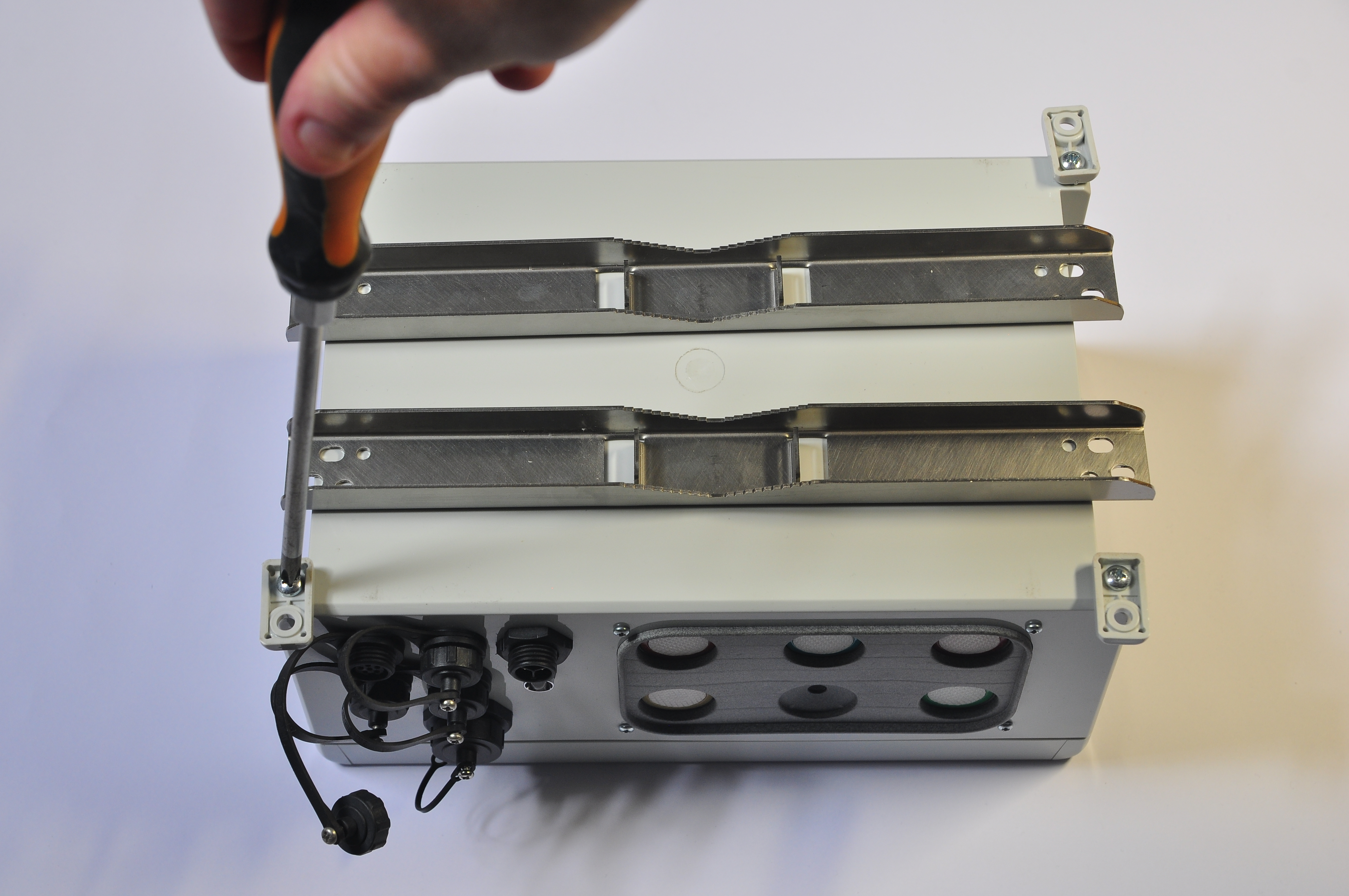
Put the two pieces in position and firmly tighten the screws.
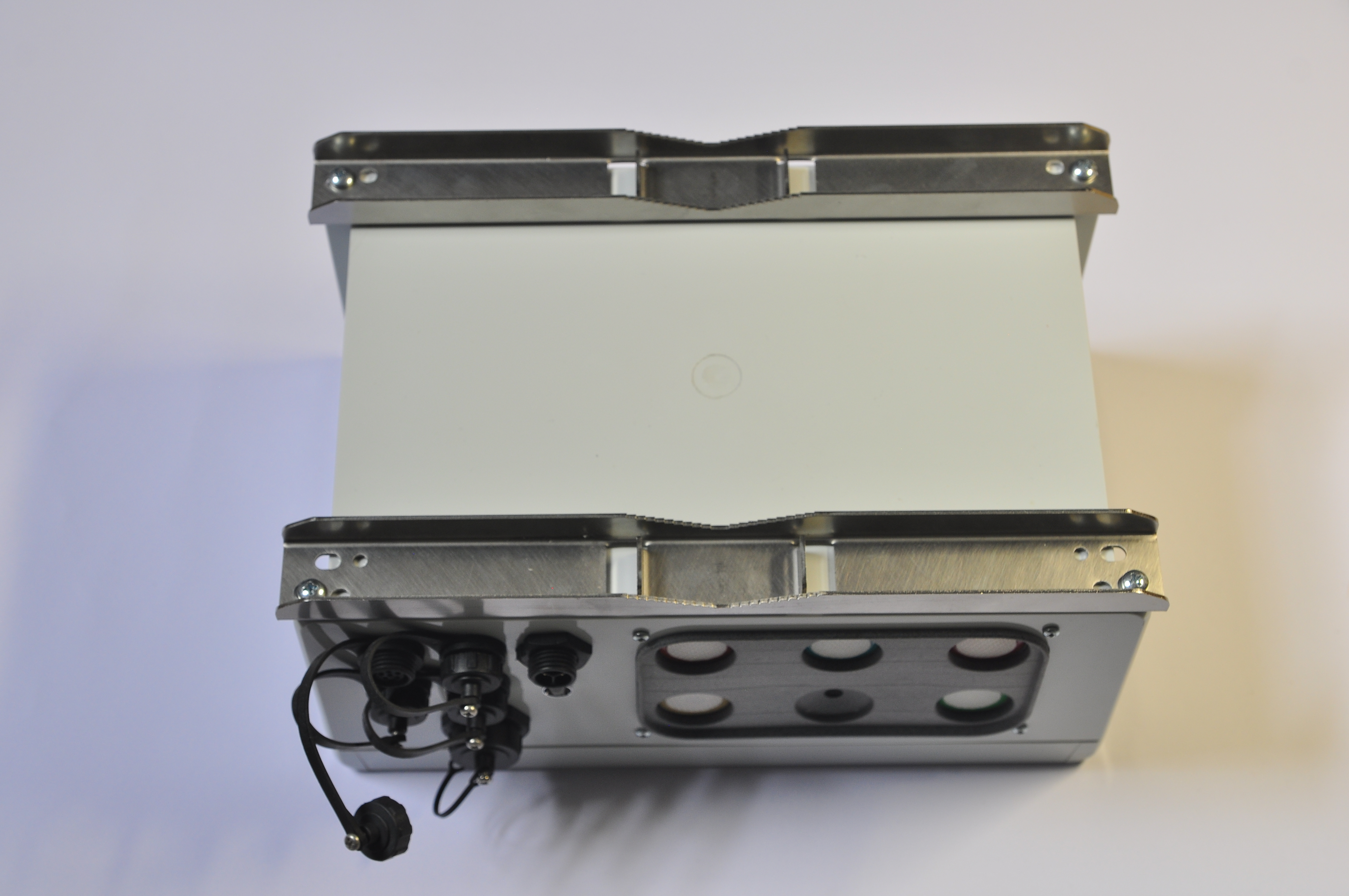
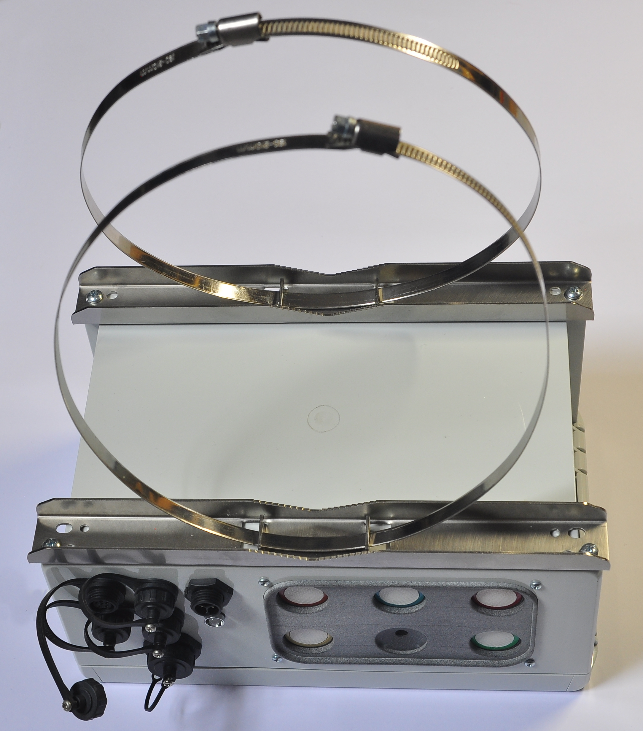
Once the bracket is installed, the Air Quality Station can now be installed on the streetlight. Open the two screw clamps, place the device in the desired position and tighten the screws firmly.
Wall installation
For proper installation, you should follow the next steps:
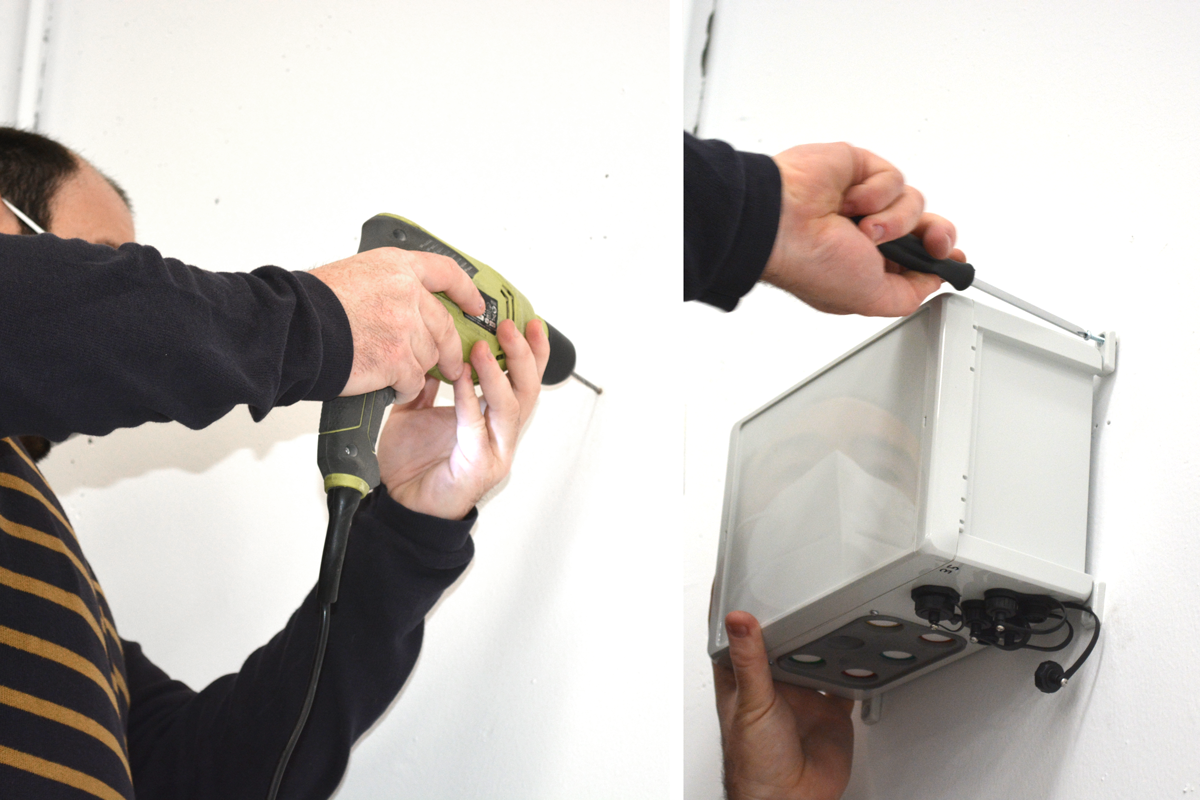
Firstly, mark 4 holes on the wall. Select an area as flat as possible. You should place the device in the final location and use the wall brackets holes as template.
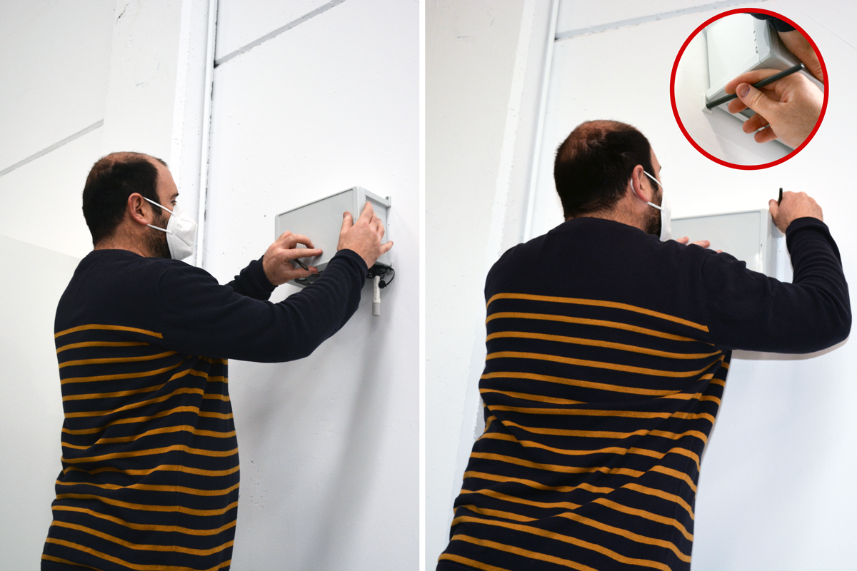
Drill the holes in the wall. The diameter must be appropriate for the plug to be used. Insert the anchors with the help of a hammer if necessary. Place the device and tighten the screws firmly.
External temperature and humidity sensor installation
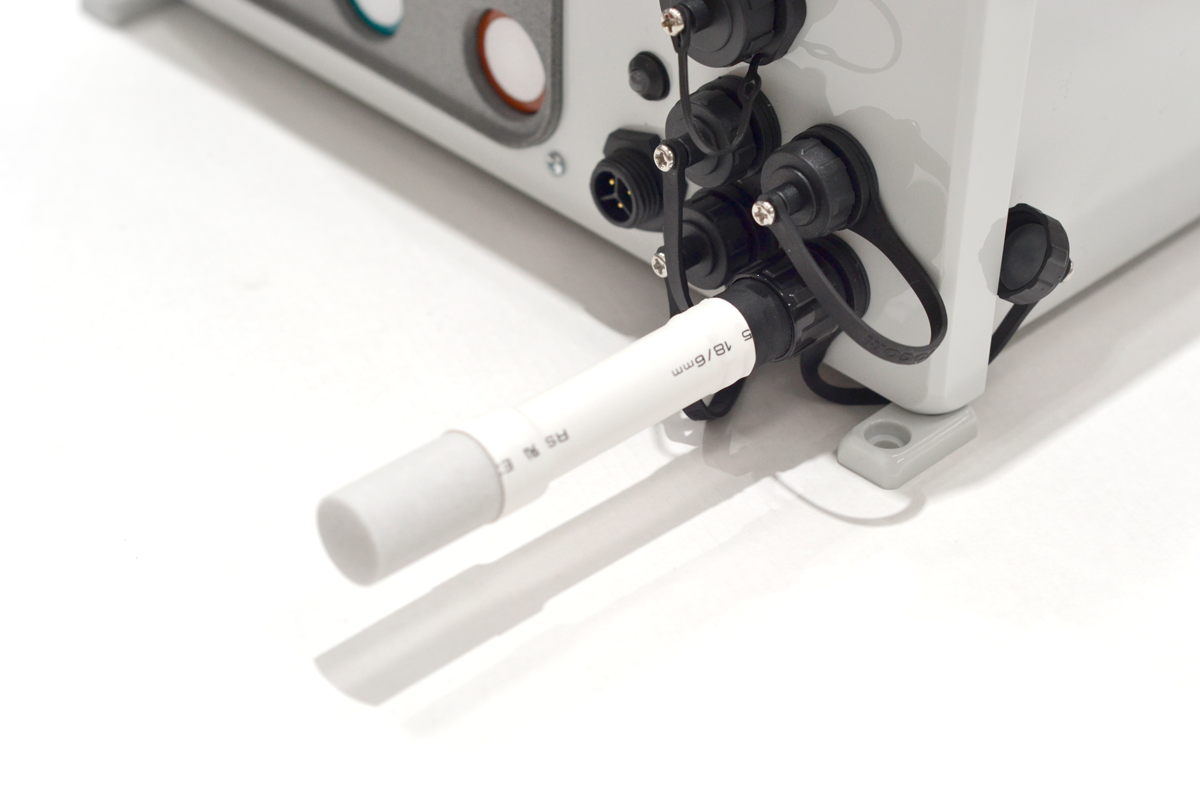
The sensor must be installed in the correct socket position as described in the next image:
Optional sensors installation
If optional sensors are used (Particulate Matter Sensor, Weather Station or Noise Level Sensor Class 2), they must be plugged before powering on the device.
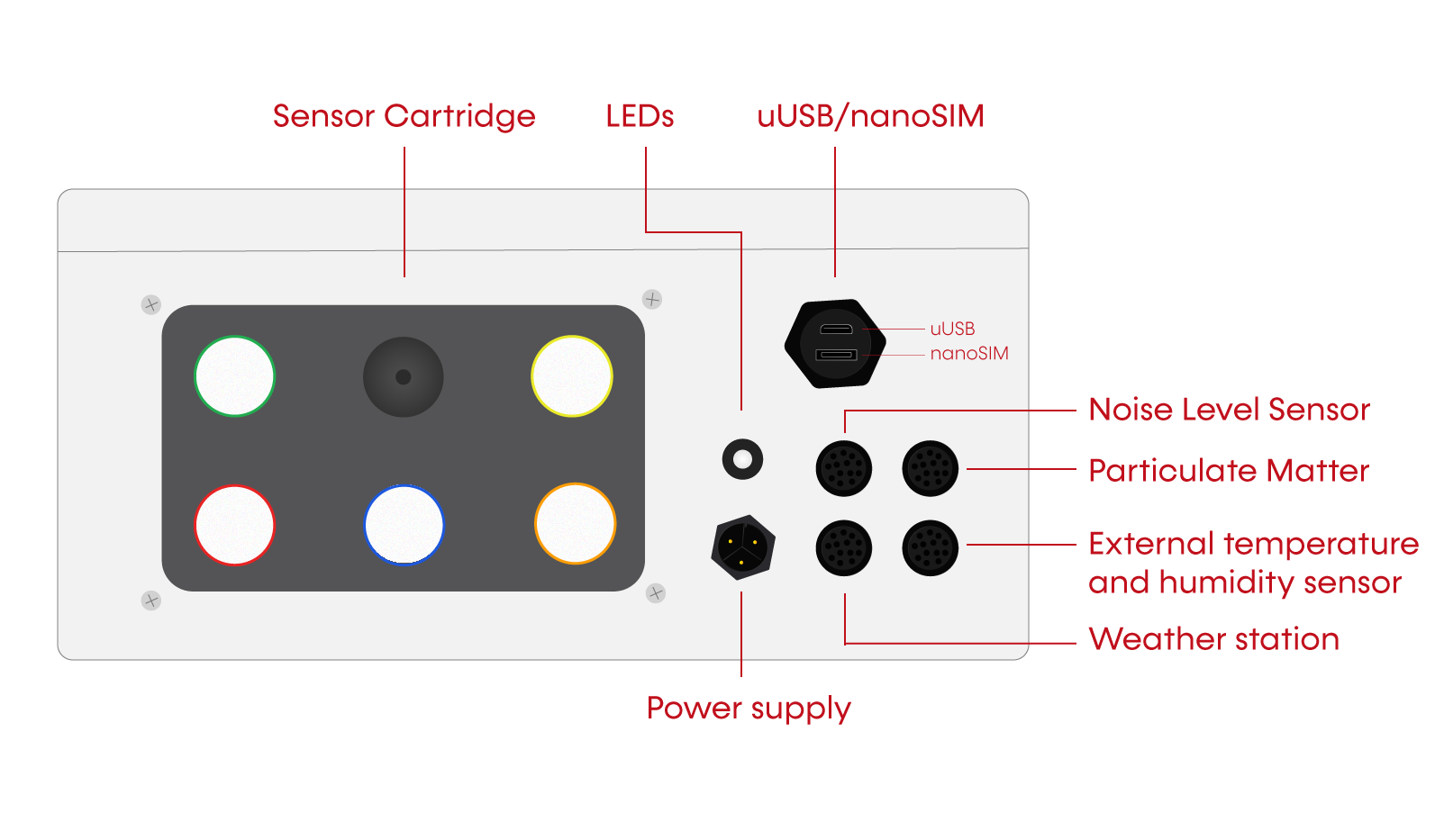
The proper socket must be used for each one of the optional sensors as described in the next image:
Particulate Matter sensor installation:
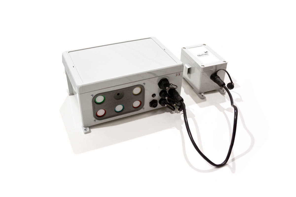
Weather Station installation:
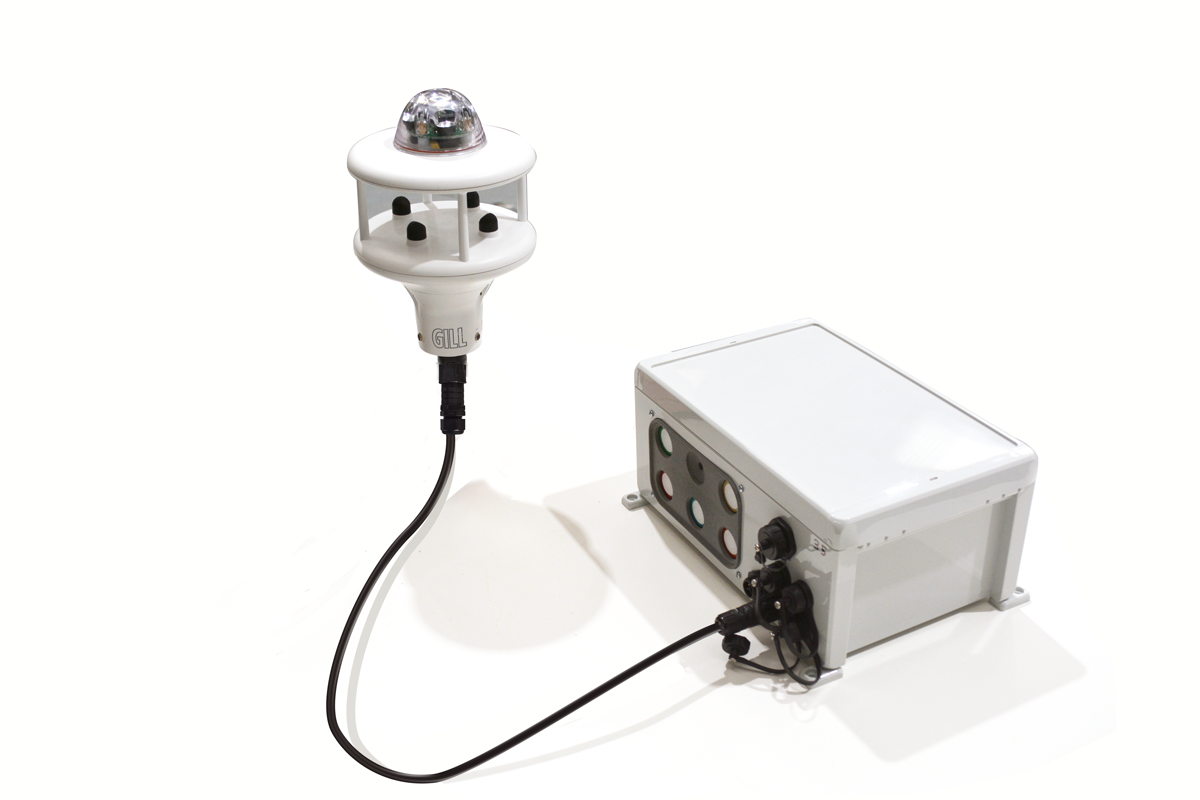
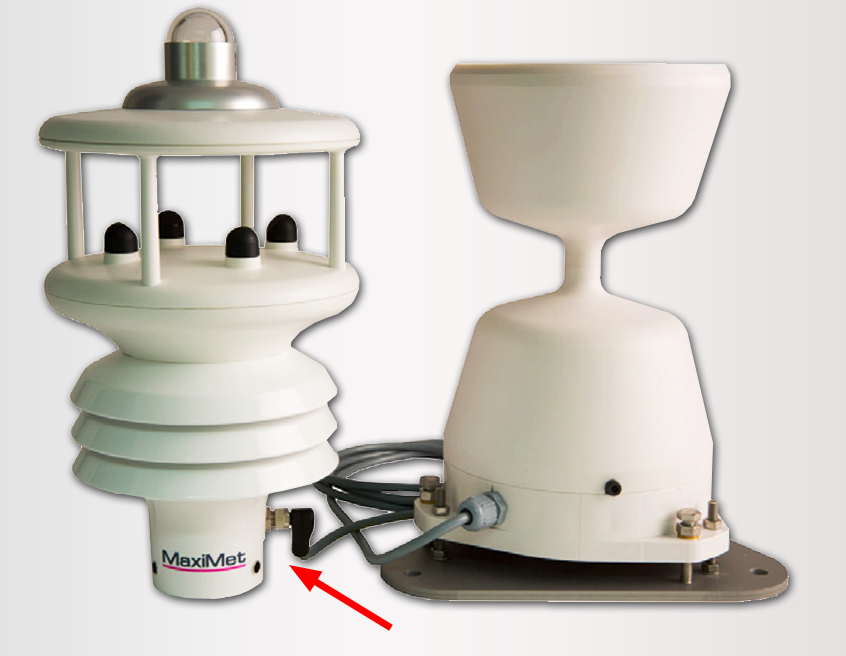
Tipping bucket accessory installation:
Noise Level Sensor Class 2 installation:
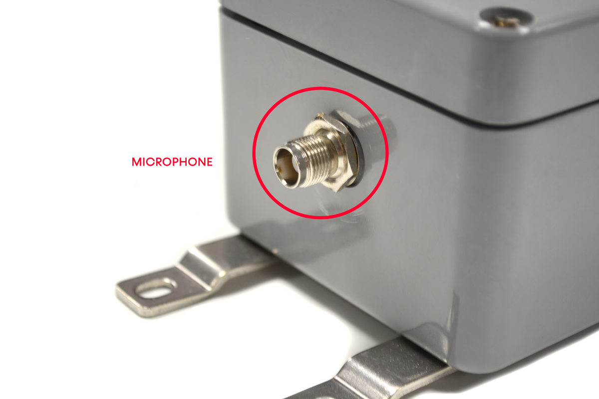
The Noise level sensor must be plugged into the correct socket:
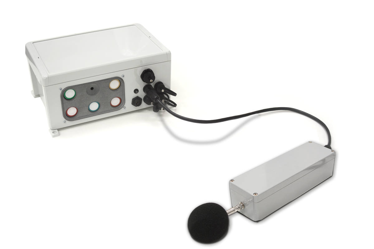
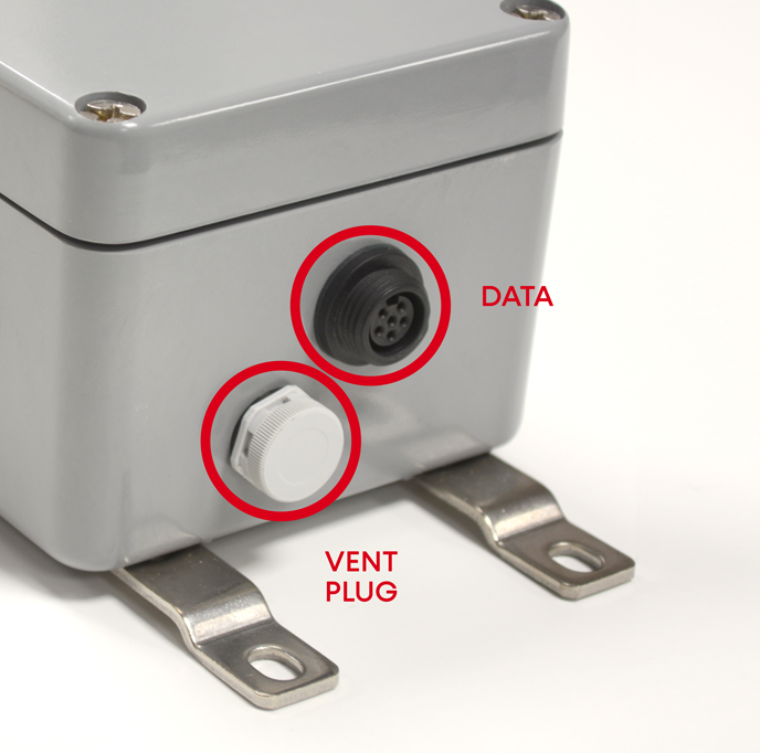
The images below show the different sockets of the Noise Level Sensor:
Powering on the device
In order to power on the device, you only have to plug the power supply connector to the 110-240 VAC supply:
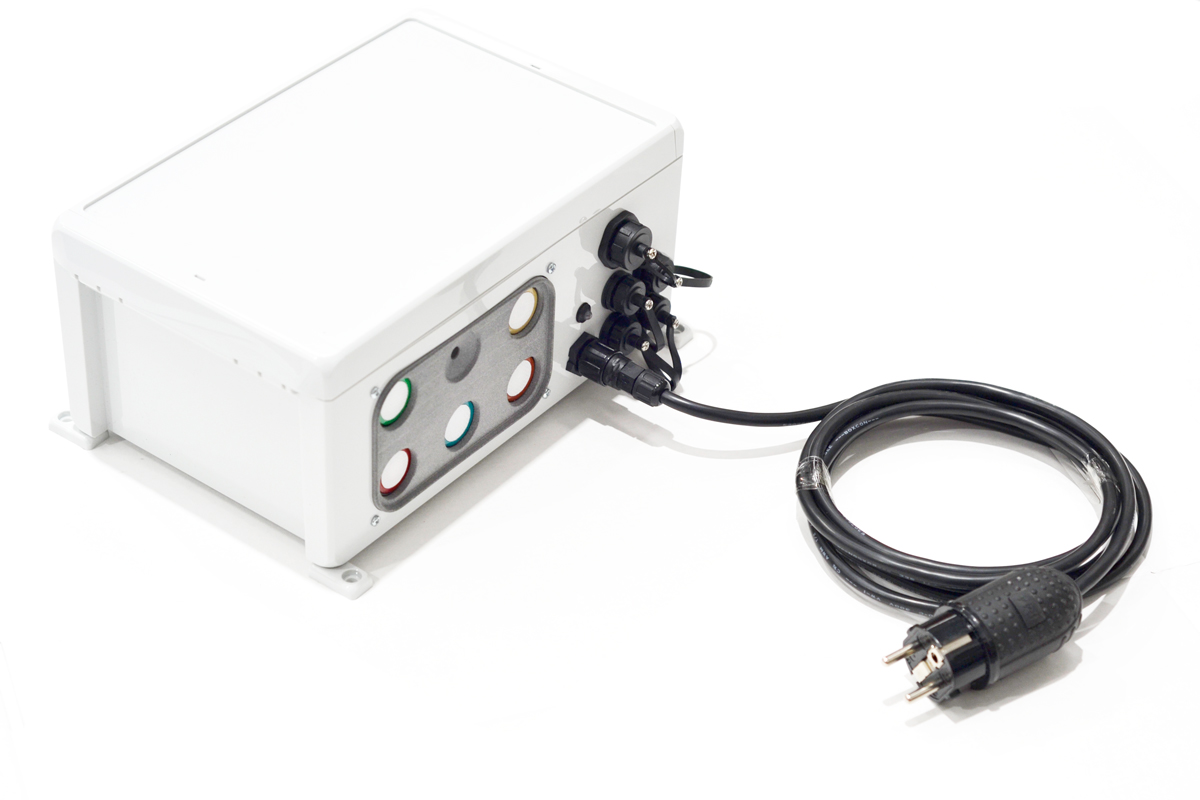
Apply extreme caution when working with high voltage (110 / 220 V). There is a real danger to installation personnel and people and things around the device (physical damage, electric shock, death, fire, etc). Make sure that the cable is securely fastened and that water or other external effects cannot affect the installation safety in the future. Act responsibly and at your own risk.
Disconnect the Air Quality Station node from mains electricity before operating inside the housing.
LED patterns
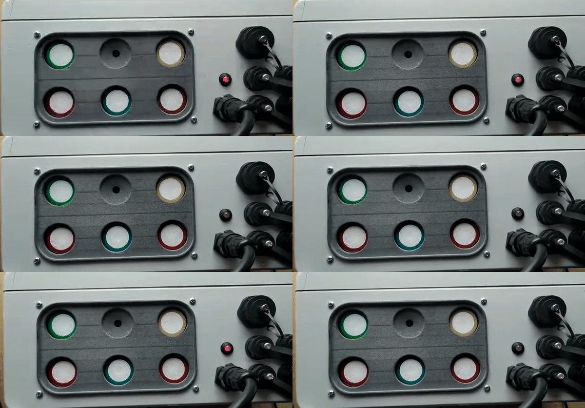
Launch bootloader pattern
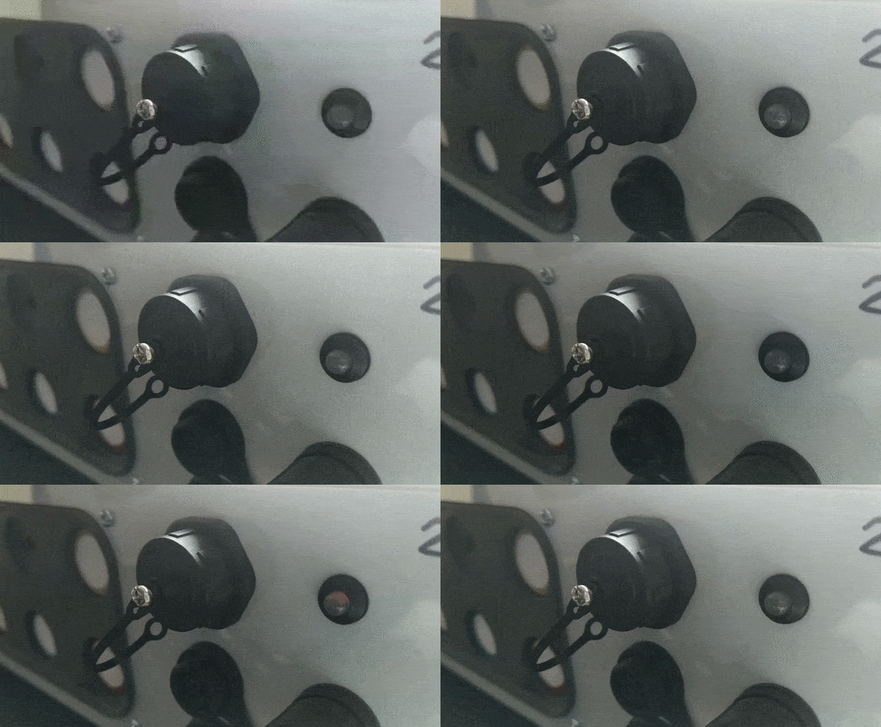
Just after powering on the device you should see how the bootloader is started by checking the bootloader pattern: 5 consecutive yellow colour blinking.
Launch Application firmware pattern
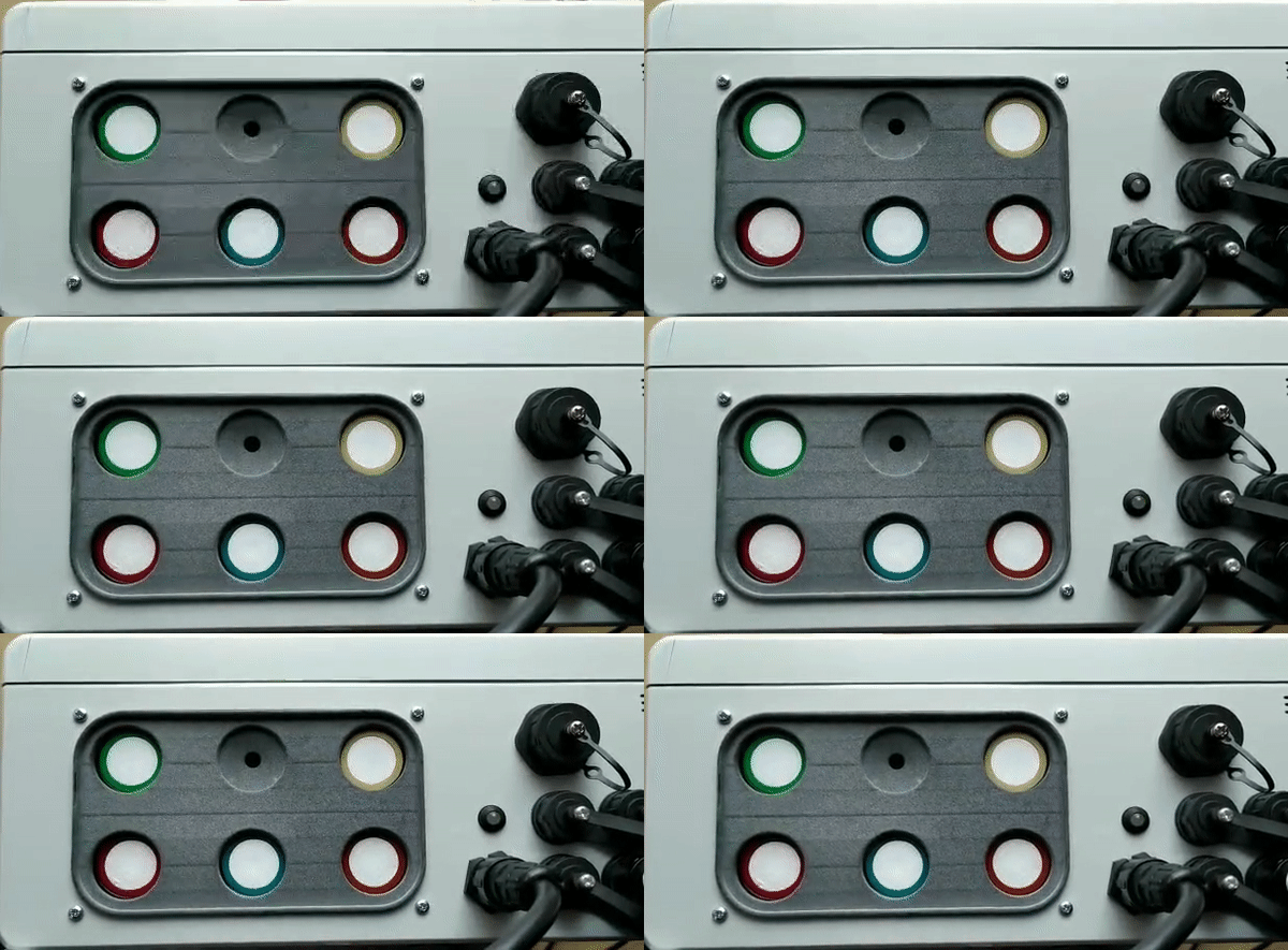
When the bootloader jumps into the "Application firmware", you should see the following pattern: a fast yellow blinking pattern followed by a single green blink event:
Error patterns
The application firmware displays different LED patterns in red colour meaning there is some kind of error. Each pattern consists of blinking the red LED for a specific number of times. Each blinking process is repeated 5 times and then an action is performed: continue or reboot the device in case of fatal error.
| Number of blinks | Error description | Action performed |
|---|---|---|
| 1 | Error loading the application firmware | Display pattern and reboot |
| 2 | LTE error posting initial device configuration in Cloud | Display pattern and reboot |
| 3 | LTE error activating the context | Display pattern and continue |
| 4 | LTE error configuring the context | Display pattern and continue |
| 5 | LTE error SIM not inserted | Display pattern and continue |
| 6 | LTE error SIM failure | Display pattern and continue |
| 7 | LTE error SIM wrong | Display pattern and continue |
| 8 | LTE error not connected to network | Display pattern and continue |
| 9 | Invalid token | Display pattern and continue |
For instance, the next clip explains the error pattern of one blink because the device does not get its profile from the Cloud service. This is normally due to a bad API key configuration:
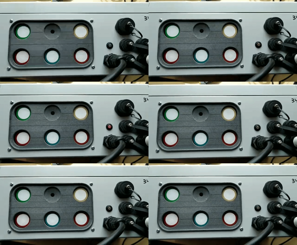
Another example: if the SIM card is not inserted, you will see a 5-blink error pattern:
