Hardware
Modular architecture
Waspmote is based on a modular architecture. The idea is to integrate only the modules needed in each device. These modules can be changed and expanded according to needs.
The modules available for integration in Waspmote are categorized in:
- ZigBee/802.15.4 XBee modules (2.4 GHz, 868 MHz, 900 MHz)
- LoRaWAN module (433/868/900 MHz)
- LoRa module (868/900 MHz)
- Sigfox module (868/900 MHz)
- NB-IoT / Cat-M module (global version, multiband)
- 4G Module (Europe/Brazil and America versions)
- WiFi module
- Bluetooth modules: Bluetooth Low Energy and Bluetooth Pro
- NFC/RFID module
- GPS module
- Sensor modules (Sensor boards)
- Storage module: SD Memory Card
Specifications
- Microcontroller: ATmega1281
- Frequency: 14.7456 MHz
- SRAM: 8 kB
- EEPROM: 4 kB
- FLASH: 128 kB
- SD Card: 16 GB
- Weight: 20 g
- Dimensions: 73.5 x 51 x 13 mm
- Temperature range: [-30 ºC, +70 ºC]*
* Temporary extreme temperatures are supported. Regular recommended usage: -20, +60 ºC.
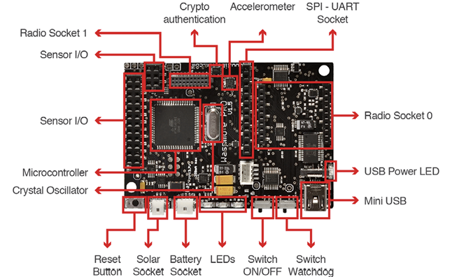
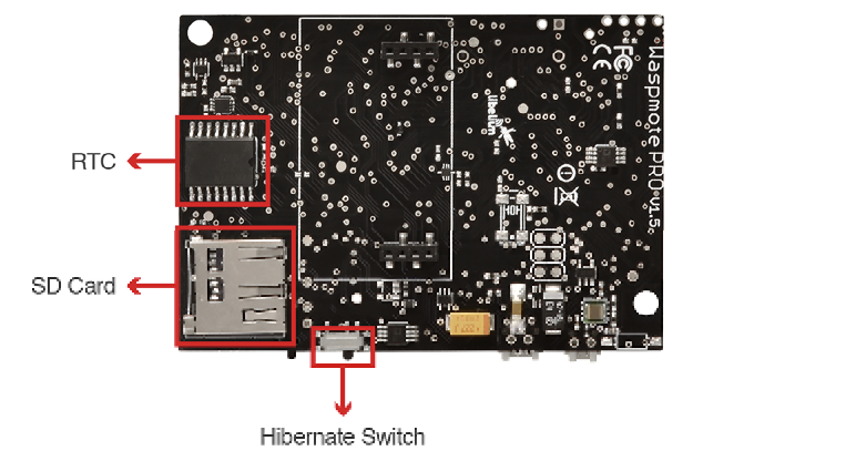
Block diagram
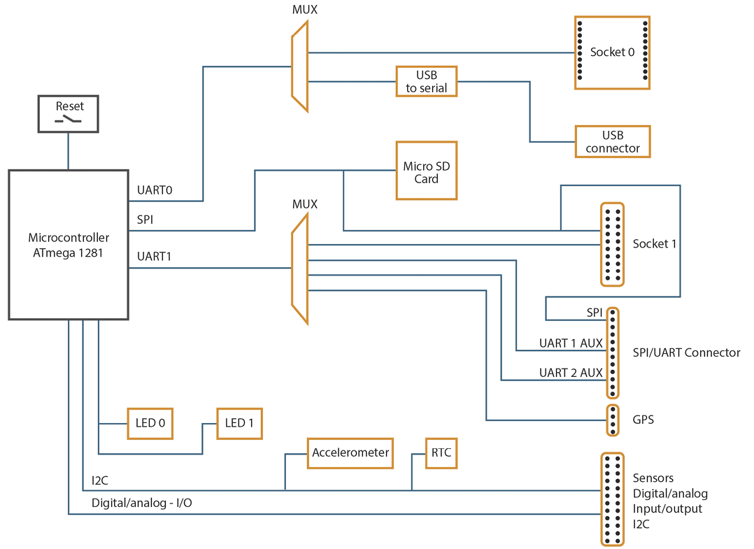
Data signals:
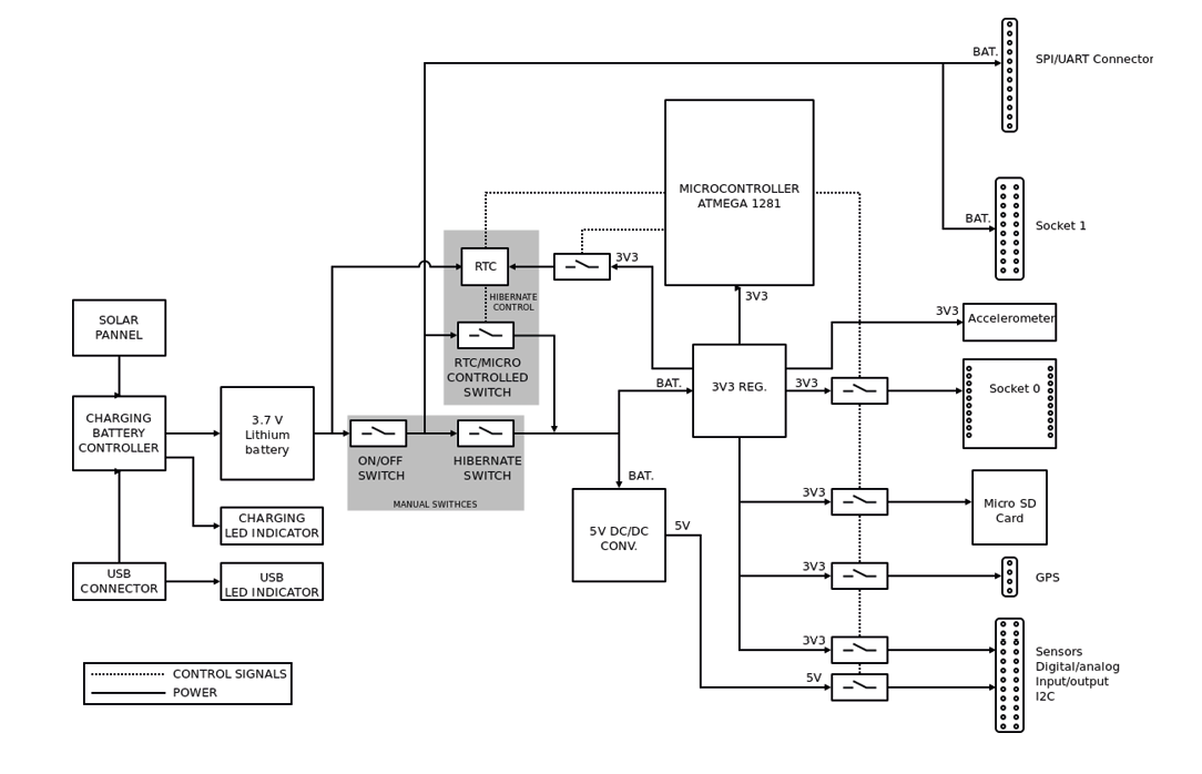
Power signals:
Electrical data
Operational values:
- Minimum operational battery voltage: 3.3 V
- Maximum operational battery voltage: 4.2 V
- USB charging voltage: 5 V
- Solar panel charging voltage: 6 - 12 V
- Battery charging current from USB: 480 mA (max current input) → 100 mA in batches since summer 2018
- Battery charging current from solar panel: 300 mA (max current input)
Absolute maximum values:
- Voltage in any pin: [-0.5 V, +3.8 V]
- Maximum current from any digital I/O pin: 40 mA
- USB power voltage: 7 V
- Solar panel power voltage: 18 V
- Charged battery voltage: 4.2 V
I/O
Waspmote can communicate with other external devices through the using different input/output ports.
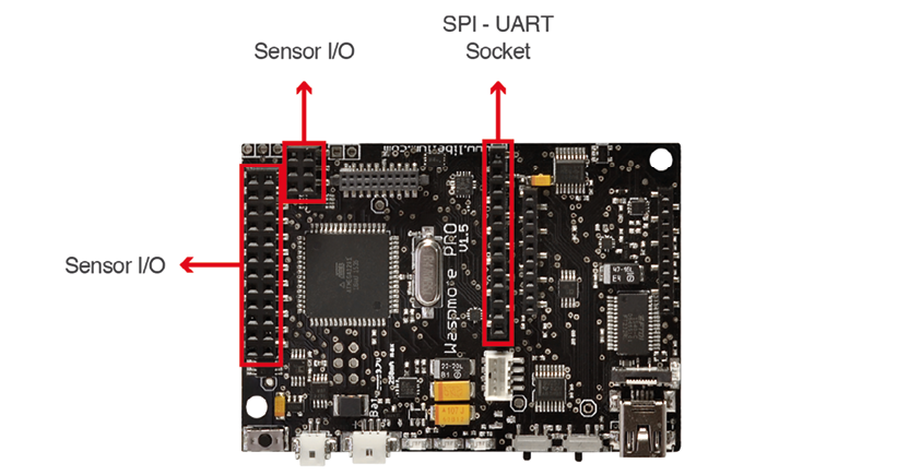
Sensor connector:
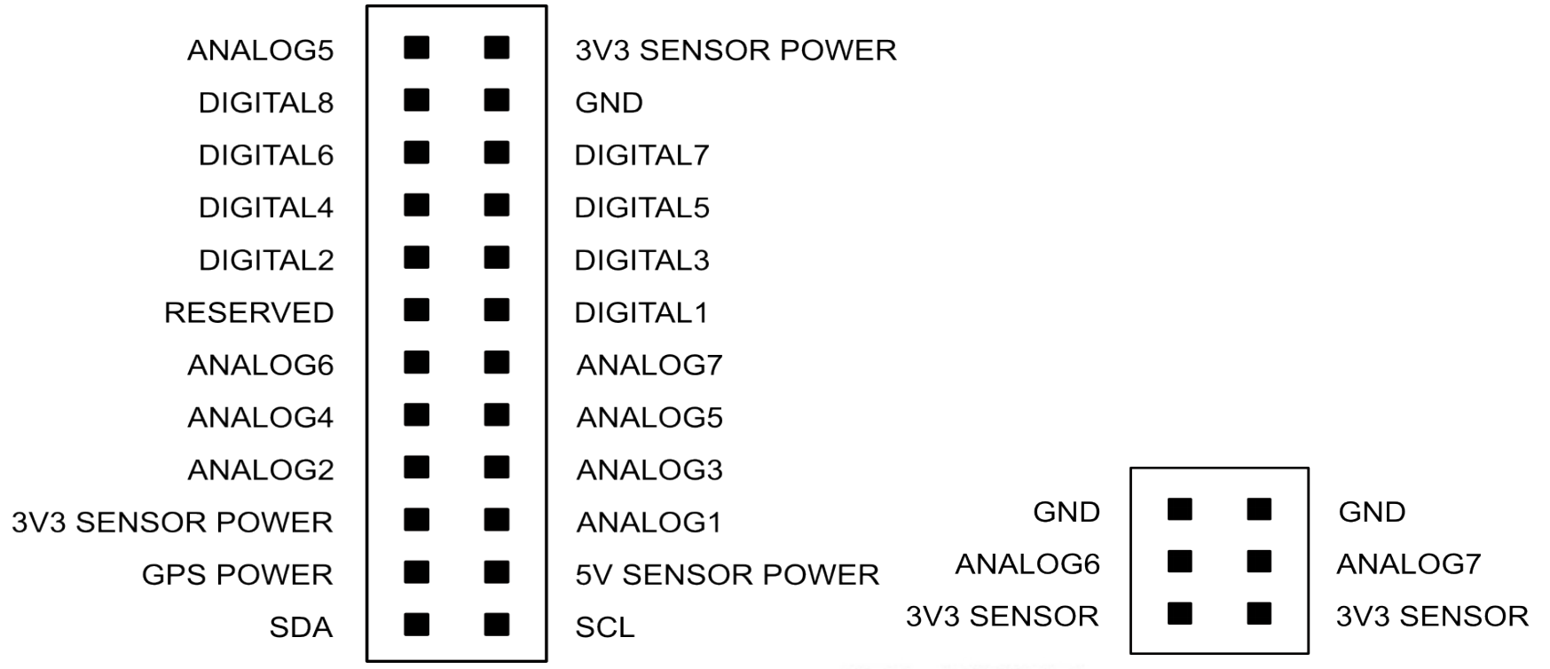
Auxiliary SPI-UART connector:

Analog pins
Waspmote has 7 accessible analog inputs in the sensor connector. Each input is directly connected to the microcontroller. The microcontroller uses a 10-bit successive approximation analog to digital converter (ADC). The reference voltage value for the inputs is 0 V (GND). The maximum value of input voltage is 3.3 V which corresponds with the microcontroller's general power voltage.
To obtain input values, the function analogRead(analog input) is used, the function's input parameter will be the name of the input to be read "ANALOG1, ANALOG2..." (see sensor connector figure). The value obtained from this function will be an integer number between 0 and 1023, 0 corresponds to 0 V and 1023 to 3.3 V.
The analog input pins can also be used as digital input/output pins. If these pins are going to be used as digital ones, the following correspondence list for pin names must be taken into account:
| Analog pin | Digital pin | |
|---|---|---|
| ANALOG1 | => | 14 |
| ANALOG2 | => | 15 |
| ANALOG3 | => | 16 |
| ANALOG4 | => | 17 |
| ANALOG5 | => | 18 |
| ANALOG6 | => | 19 |
| ANALOG7 | => | 20 |
{
    val = analogRead(ANALOG1);
}
Digital pins
Waspmote has digital pins which can be configured as input or output depending on the needs of the application. The voltage values corresponding to the different digital values would be:
LOW: 0 V for logic 0HIGH: 3.3 V for logic 1
The instructions for control of digital pins are:
{
    // set DIGITAL3 pin as input and read its value
    pinMode(DIGITAL3, INPUT);
    val = digitalRead(DIGITAL3);

    // set DIGITAL3 pin as output and set it LOW
    pinMode(DIGITAL3 ,OUTPUT);
    digitalWrite(DIGITAL3, LOW);
}
PWM
DIGITAL1 pin can also be used as output PWM (Pulse Width Modulation) with which an analog signal can be "simulated". It is actually a square wave between 0 V and 3.3 V for which the proportion of time when the signal is high can be changed (its working cycle) from 0% to 100%, simulating a voltage of 0 V (0%) to 3.3 V (100%).The resolution is 8 bit, so up to 255 values between 0-100% can be configured. The instruction to control the PWM output is analogWrite(DIGITAL1, value); where value is the analog value (0-255).
{
    analogWrite(DIGITAL1, 127);
}
UART
There are 2 UARTs in Waspmote: UART0 and UART1. Besides, there are several ports which might be connected to these UARTs through 2 different multiplexers, one for each UART.
- UART0 is shared by the USB port and the Socket0. This socket is used for XBee modules, LoRaWAN module, LoRa module, Sigfox module, RFID/NFC module, Bluetooth modules, WiFi module, RS-485 module, etc. The multiplexer in this UART controls the data signal which by default is always switched to Socket0. When the USB needs to send info through the UART0, the multiplexer is momentarily switched to the USB port and set back again to Socket0 after printing.
- UART1 is shared by 4 ports: Socket1, GPS socket, Auxiliar1 and Auxiliar2 sockets. It is possible to select in the same program which of the 4 ports is connected to UART1 in the microcontroller. UART1 multiplexer configuration is carried out using the following instructions:
{
    Utils.setMuxAux1(); // set Auxiliar1 socket
    Utils.setMuxAux2(); // set Auxiliar2 socket
    Utils.setMuxGPS(); // set GPS socket
    Utils.setMuxSocket1(); // set Socket1
}
I2C
The I2C communication bus is also used in Waspmote where several devices are connected in parallel: the accelerometer, a crypto-authentication memory and the RTC. In all cases, the microcontroller acts as master while the other devices connected to the bus are slaves.
SPI
The SPI port on the microcontroller is used for communication with the micro SD card. All operations using the bus are performed clearly by the specific library. The SPI port is also available in the SPI/UART connector and Socket0.
USB
USB is used in Waspmote for communication with a computer or compatible USB devices. This communication allows the microcontroller's program to be loaded.
For USB communication, microcontroller's UART0 is used. The FT232RL chip carries out the conversion to USB standard.
Real Time Clock -- RTC
Waspmote has a built in Real Time Clock - RTC, which keeps it informed of the time. This allows Waspmote to be programmed to perform time-related actions such as:
"Sleep for 1h 20 min and 15sec, then wake up and perform the following action.."
Or even programs to perform actions at absolute intervals, e.g.:
"Wake on the 5th of next month at 00:20 and perform the following action.."
All RTC programming and control is done through the I2C bus.
Alarms:
Alarms can be programmed in the RTC specifying day/hour/minute/second. That allows total control about when the mote wakes up to capture sensor values and perform actions programmed on it. This allows Waspmote to be in the saving energy modes (Deep Sleep and Hibernate) and makes it wake up just at the required moment.
As well as relative alarms, periodic alarms can be programmed by giving a time measurement, so that Waspmote reprograms its alarm automatically each time one event is triggered.
The RTC chosen is the Maxim DS1337C, which operates at a frequency of 32.768 kHz (a second divisor value which allows it to quantify and calculate time variations with high precision).
The RTC is powered by the battery. When the battery is connected, the RTC is powered on. However, the user must keep in mind that if the battery is removed or out of load, then time data will be not maintained. This is the reason we suggest to use RTC time as 'relative' and not 'absolute' (see Programming Guide for more info).
A coin or button battery is not needed. They have a limited life and therefore Waspmote can have a much longer power life expectancy. This is so because the RTC is powered from the "main" battery which has a much bigger charge.
The RTC is responsible for waking Waspmote up from sleep modes like Deep Sleep and Hibernate. This makes possible to use its battery to just power the RTC in sleep modes. The RTC controls when the device has to wake up and perform a particular action. This permits a consumption of 7 uA in the Hibernate mode. Please refer to "Energy System" section for more information.
Related API libraries: WaspRTC.h, WaspRTC.cpp
All information about their programming and operation can be found in the RTC Programming Guide.
All the documentation is located in the Development section in the Libelium website.
LEDs
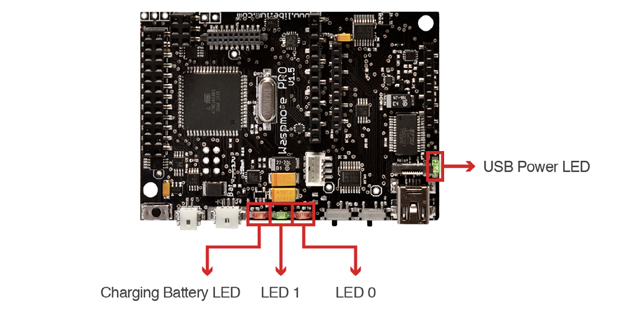
The Waspmote LEDs are:
- Charging battery LED indicator: A red LED indicating that there is a battery connected in Waspmote which is being charged. The charging can be done through a mini-USB cable or through a solar panel connected to Waspmote. Once the battery is completely charged, the LED switches off automatically.
- LED0 (programmable LED): A red LED is connected to the microcontroller. It is totally programmable by the user from the program code. In addition, the LED0 indicates when Waspmote resets, blinking each time a reset on the board is carried out.
- LED1 (programmable LED): A green LED is connected to the microcontroller. It is totally programmable by the user from the program code.
- USB Power LED indicator: A green LED which indicates when Waspmote is connected to a compatible USB port either for battery charging or programming. When the LED is on, it indicates that the USB cable is connected correctly. When the USB cable is removed, this LED will switch off automatically.
Please refer to Waspmote Utilities guide for more information.