Sensors
Accelerometer
Waspmote has a built-in acceleration sensor LIS3331LDH, by STMicroelectronics, which informs the mote of acceleration variations experienced on each one of the 3 axes (X, Y, Z).
The integration of this sensor allows the measurement of acceleration on the 3 axes (X, Y, Z), establishing 4 kinds of events: Free Fall, inertial wake up, 6D movement and 6D position which are explained in the Interruptions Programming Guide.
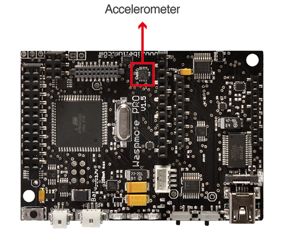
The LIS331DLH has dynamically user-selectable full scales of ±2g/±4g/±8g and it is capable of measuring accelerations with output data rates from 0.5 Hz to 1 kHz.
The device features ultra low-power operational modes that allow advanced power saving and smart sleep to wake-up functions.
The accelerometer has several power modes, the output data rate (ODR) will depend on the power mode selected. The power modes and output data rates are shown in this table:
| Power mode | Output data rate (Hz) |
|---|---|
| Power down | - |
| Normal mode | 1000 |
| Low-power 1 | 0.5 |
| Low-power 2 | 1 |
| Low-power 3 | 2 |
| Low-power 4 | 5 |
| Low-power 5 | 10 |
This accelerometer has an auto-test capability that allows the user to check the functioning of the sensor in the final application. Its operational temperature range is between -40 ºC and +85 ºC.
The accelerometer communicates with the microcontroller through the I2C interface. The pins that are used for this task are the SCL pin and the SDA pin, as well as another interruption pin to generate the interruptions.
The accelerometer has 4 types of event which can generate an interrupt: free fall, inertial wake up, 6D movement and 6D position.
These thresholds and times are set in the WaspACC.h file.
To show the ease of programming, an extract of code about how to get the accelerometer values is included below:
{
    ACC.ON();
    ACC.getX();
    ACC.getY();
    ACC.getZ();
}
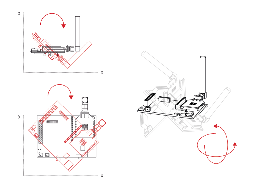
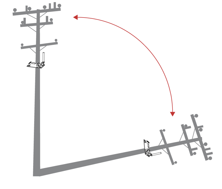
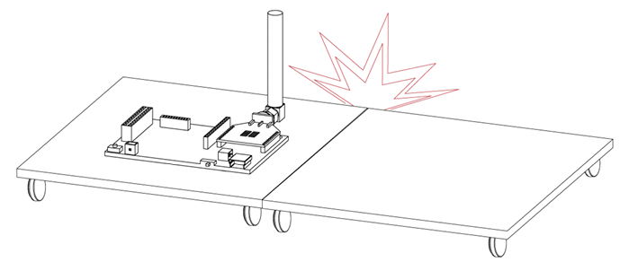
Some figures with possible uses of the accelerometer are shown below:
Rotation and twist:
Free fall of objects in which it is installed:
Crash:
More information about interruptions generated by the accelerometer can be found in the chapter "Interruptions" and in the Interruptions Programming Guide.
Related API libraries: WaspACC.h, WaspACC.cpp
All information about their programming and operation can be found in the Accelerometer Programming Guide.
All the documentation is located in the Development section in the Libelium website.
Integration of new sensors
The Waspmote design is prepared for the integration of both input (sensors) and output (actuators) which allows to grow the wide range of existing Waspmote sensor boards. The new sensors can be connected to Waspmote's 2x12 and 1x12 pin connectors, which permit to use 16 input and output signals, 7 of which can be used as analog inputs and 1 as a PWM (Pulse Width Modulation) output signal. Besides, there is a line to ground, 3.3 V and 5 V power feeds, 2 selectable connections to the serial communication (UART) inputs and outputs, connection to the 2 lines of the (I2C) SCL and SDA Inter-Integrated Circuit bus, and connection to inputs for high level and low level interrupt. An image of the Waspmote output connectors can be seen in the "I/O" section.
The management the 2 power lines (3.3 and 5 V) for the sensor boards (described in more depth in section "Sensors" → Power) is carried out through 2 solid state switches which allow the continuous flow of a current of up to 200 mA and whose control can be programmed using the functions included in the WaspPWR library, described in the files WaspPWR.h and WaspPWR.cpp.
The input and output voltage values for both digital and analog pins will be between 0 V and 3.3 V, logic zero ('0') being found in values less than 0.5 V and logic one ('1') in values higher than 2.30 V. To read analog signals, the microcontroller has a 10-bit analog-to-digital converter which allows a resolution of 3 mV. Waspmote also has one 8-bit resolution PWM output pin for the generation of analog signals. Information on the libraries and instructions used for reading and writing on these pins can be found in the API manual.
Waspmote includes 2 interruption pins, a low level (TXD1) one and a high level (RXD1) one, which offer an alternative to reading the sensors by survey, allowing the microcontroller to be woken up when an event occurs (such as exceeding a certain threshold in a comparator) which generates a change in a digital signal connected to one of the above pins, facilitating the sensor reading only at the moments when a remarkable event occurs.
This option is especially recommended for low consumption sensors that may remain active for long periods of time. Reading by survey (switched on and cyclical sensor reading after a set time) is more appropriate for those that, in addition to showing greater consumption, do not require monitoring that generates an alarm signal. The interruptions can be managed using the warning functions and vectors (flags) defined in the Winterruptions library, file Winterruptions.c. More can be learnt about their use in the Interruptions Programming Guide.
Sensors reading can generate 3 types of response: storage of collected data (on the SD card), wireless transmission of data (via wireless module) or automatic activation through an actuator directly controlled by the microcontroller's output signals or through a switch or relay.
Sensor boards
The integration of sensors requiring some type of electronic adaptation stage or signal processing prior to reading by the microcontroller is carried out by the various microcontroller sensor boards. Connection between these and the mote takes place pin to pin using the two 2x12 and 1x12 connectors mentioned in the section "Hardware" → I/O. Currently, Waspmote has the following integration sensor boards:
GASES PRO*
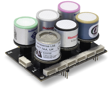
(*) Calibrated gas sensors are manufactured once the order has been placed to ensure maximum durability of the calibration feature. Manufacturing process and delivery may take from 4 to 6 weeks. Lifetime of calibrated gas sensors is 6 months working at its maximum accuracy. We strongly encourage our customers to buy extra gas sensor probes to replace the originals after that time to ensure maximum accuracy and performance.
APPLICATIONS
- City pollution: CO, NO, NO2 , O3 , SO2 , Particle Matter - Dust
- Air Quality Index calculation: SO2 , NO2 , Particle Matter - Dust, CO, O3 , NH3
- Emissions from farms and hatcheries: CH4 , H2S, NH3
- Greenhouse management: CO2 , CH4 , Humidity
- Control of chemical and industrial processes: CH4 , SO2 , CO2
- Indoor air quality: CO2 , CO, Particle Matter - Dust, O3
- Forest fires: CO, CO2
SENSORS
- Carbon Monoxide – CO
- Carbon Dioxide – CO2
- Molecular Oxygen – O2
- Ozone – O3
- Nitric Oxide – NO
- Nitric Dioxide – NO2
- Sulfur Dioxide – SO2
- Ammonia – NH3
- Methane – CH4 – and other combustible gases
- Hydrogen Sulfide – H2S
- Particle Matter (PM1 / PM2.5 / PM10) – Dust Sensor [only for Plug & Sense!]
- Temperature, Humidity and Pressure
EVENTS
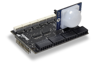
APPLICATIONS
- Security: Hall effect (doors and windows), person detection PIR
- Emergencies: Presence detection and water level sensors, temperature
- Control of goods in logistics.
SENSORS
- Pressure/Weight
- Hall Effect
- Temperature, Humidity and Pressure
- Liquid Presence
- Liquid Level
- Liquid flow
- Luminosity (Luxes)
- Presence (PIR)
- Ultrasound (distance measurement)
SMART WATER
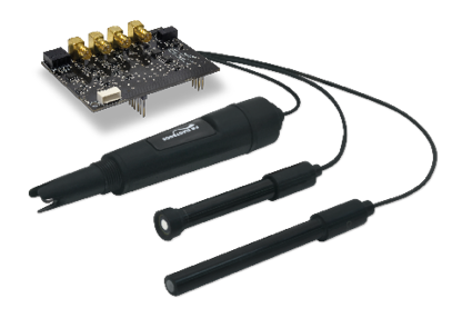
APPLICATIONS
- Potable water monitoring: pH, ORP, Dissolved Oxygen (DO), Nitrates, Phosphates
- Chemical leakage detection in rivers: Extreme pH values signal chemical spills, Dissolved Oxygen (DO)
- Swimming pool remote measurement: pH, Oxidation-Reduction Potential (ORP)
- Pollution levels in the sea: Temperature, Conductivity (Salinity), pH, Dissolved Oxygen (DO) and Nitrates
SENSORS
- pH
- Oxidation-Reduction Potential (ORP)
- Dissolved Oxygen (DO)
- Conductivity
- Temperature
SMART WATER XTREME
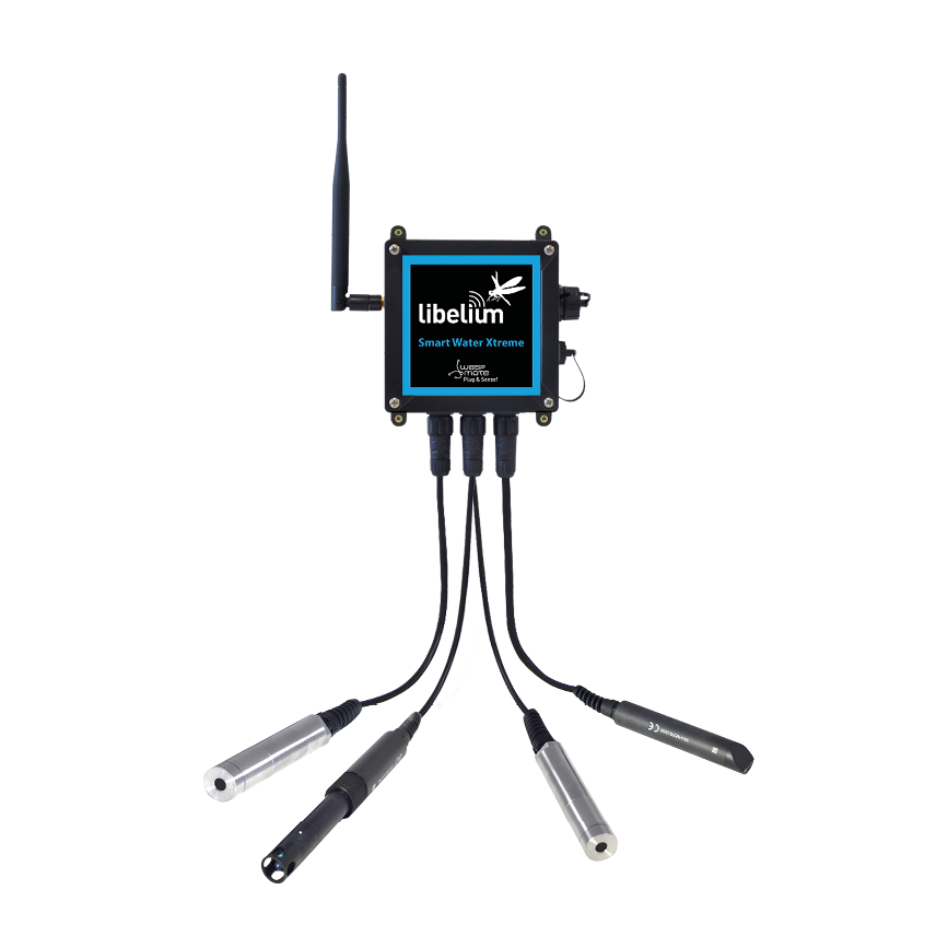
This sensor board is only available for Plug & Sense!.
APPLICATIONS
- Industrial and public sewage treatment plants
- Wastewater management (nitrification and de-nitrification)
- Surface water monitoring
- Fish farming, aquaculture
- Drinking water monitoring
- Process engineering plants
SENSORS
- Optical dissolved oxygen and temperature OPTOD
- Titanium optical dissolved oxygen and temperature OPTOD
- pH, ORP and temperature PHEHT
- Conductivity, salinity and temperature C4E
- Inductive conductivity, salinity and temperature CTZN
- Turbidity and temperature NTU
- Suspended solid, turbidity, sludge blanket and temperature MES5
- COD, BOD, TOC, SAC254 and temp StacSense, 2 mm path
- COD, BOD, TOC, SAC254 and temp StacSense, 50 mm path
- Total coliform bacteria, TLF, turbidity and temperature Proteus
- Manta+ 35A
- Manta+ 35B
- Chlorophyll sensor
- BGA sensor
- Organic matter sensor CDOM/ FDOM
- Ammonium
- Nitrate
- Chloride
- Sodium
- Calcium
- Bromide
- Total Dissolved Gas TDG
- Rhodamine
- Crude oil
- Refined oil
- Flourescein
- Optical brighteners
- Tryptophan
- Radar level VEGAPULS C21
SMART WATER IONS
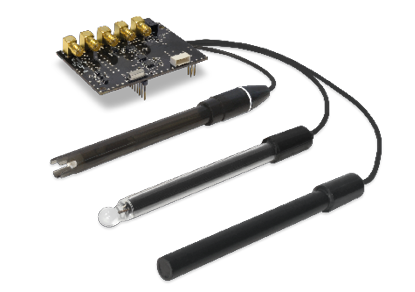
APPLICATIONS
- Drinking water quality control: Calcium (Ca 2+ ), Iodide (I - ), Chloride (Cl - ), Nitrate (NO 3- ), Magnesium (Mg 2+ ), Sodium (Na + ), pH
- Agriculture water monitoring: Calcium (Ca 2+ ), Nitrate (NO 3- ), Magnesium (Mg 2+ ), Sodium (Na + ), Potassium (K + ), Ammonium (NH 4+ ), pH
- Swimming pools: Bromide (Br - ), Chloride (Cl - ), Fluoride (F - ), pH
- Waste water treatment: Cupric (Cu 2+ ), Silver (Ag + ), Lithium (Li + ), Nitrite (NO 2- ), Perchlorate (ClO 4- ), pH
SENSORS
- Ammonium (NH 4+ )
- Bromide (Br - )
- Calcium (Ca 2+ )
- Chloride (Cl - )
- Cupric (Cu 2+ )
- Fluoride (F - )
- Iodide (I - )
- Lithium (Li + )
- Nitrate (NO 3- )
- Nitrite (NO 2- )
- Magnesium (Mg 2+ )
- Perchlorate (ClO 4- )
- Potassium (K + )
- Silver (Ag + )
- Sodium (Na + )
- pH
- Temperature
SMART CITIES PRO*
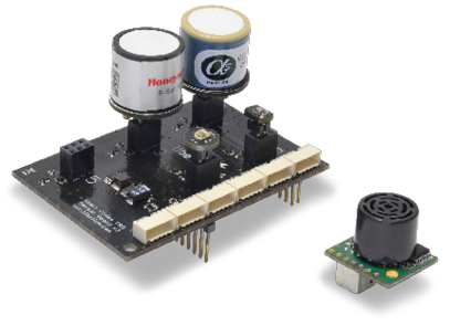
This sensor board is only available for Plug & Sense!.
(*) Calibrated gas sensors are manufactured once the order has been placed to ensure maximum durability of the calibration feature. Manufacturing process and delivery may take from 4 to 6 weeks. Lifetime of calibrated gas sensors is 6 months working at its maximum accuracy. We strongly encourage our customers to buy extra gas sensor probes to replace the originals after that time to ensure maximum accuracy and performance.
APPLICATIONS
- Noise maps: Monitor in real time the acoustic levels in the streets of a city
- Air quality: Detect the level of gases and particulates in the air
- Waste management: Measure the garbage levels in bins to optimize the trash collection routes
SENSORS
- Carbon Monoxide – CO
- Carbon Dioxide – CO2
- Molecular Oxygen – O2
- Ozone – O3
- Nitric Oxide – NO
- Nitric Dioxide – NO2
- Sulfur Dioxide – SO2
- Ammonia – NH3
- Methane – CH4 – and other combustible gases
- Hydrogen Sulfide – H2S
- Particle Matter (PM1 / PM2.5 / PM10) – Dust Sensor [only for Plug & Sense!]
- Temperature, Humidity and Pressure
- Noise level (dBA) [only for Plug & Sense!]
- Ultrasound (distance measurement)
- Luminosity (Luxes)
SMART PARKING
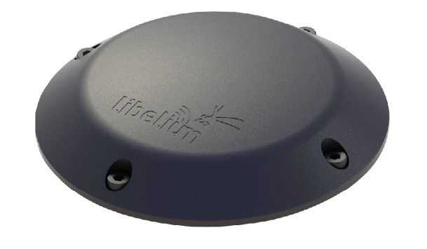
APPLICATIONS
- Car detection for available parking information
- Detection of free parking slots outdoors
- Parallel, perpendicular and angled parking slots control
- LoRaWAN connectivity (EU, US, APAC / LATAM / AU / AU915, IN, APAC / LATAM / AU / AS923 and JP / KR)
- Extreme battery life
- Surface-mount enclosure, fast installation
- Easy configuration, remote management from the cloud
SENSORS
- Radar
- Magnetic field
- Temperature
AGRICULTURE PRO
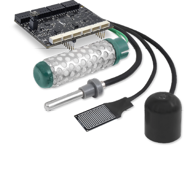
APPLICATIONS
- Precision Agriculture: Leaf temperature, fruit diameter
- Irrigation systems: Soil moisture, leaf wetness
- Greenhouses: Solar radiation, humidity, temperature
- Weather stations: Anemometer, wind vane, pluviometer
SENSORS
- Air Temperature, Humidity and Pressure
- Soil Temperature / Moisture
- Leaf Wetness
- Atmospheric Pressure
- Solar Radiation - PAR
- Ultraviolet Radiation - UV
- Trunk Diameter
- Stem Diameter
- Fruit Diameter
- Anemometer
- Wind Vane
AGRICULTURE XTREME
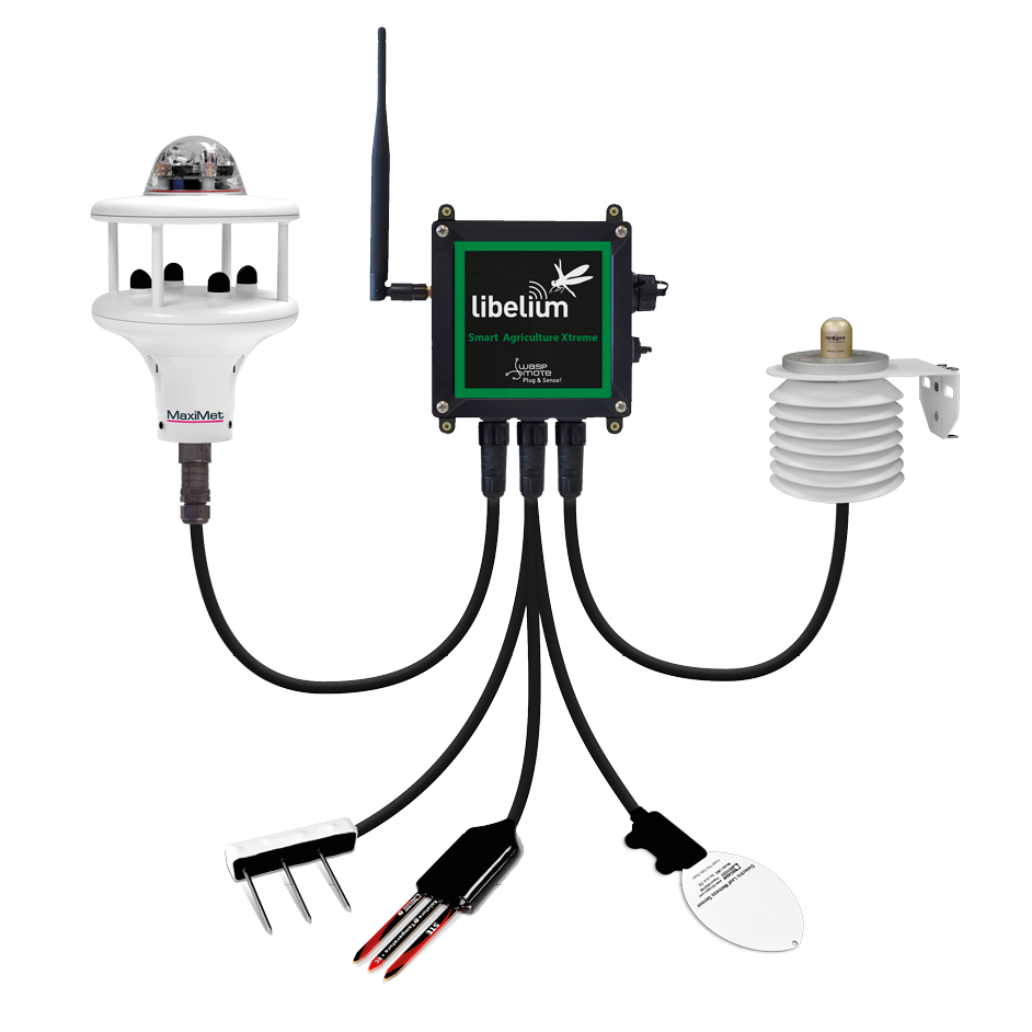
This sensor board is only available for Plug & Sense!.
APPLICATIONS
- Precision Agriculture
- Irrigation systems
- Greenhouses
- Weather monitoring
- Soil management
- Accurate fruit observation
SENSORS
- Non-contact surface temperature measurement SI-411
- Leaf and flower bud temperature SF-421
- Soil oxygen level O-411
- Shortwave radiation SP-510
- Solar radiation (PAR) SQ-110
- Ultraviolet radiation (UV) SU-100
- Air temperature, humidity and pressure
- Volumetric water content and soil temperature TEROS 11
- Conductivity, water content and soil temperature TEROS 12
- Soil water potential TEROS 21
- Vapor pressure, humidity, temperature and air pressure sensor probe (ATMOS 14)
- Leaf wetness Phytos 31
- Trunk Diameter DC2
- Stem Diameter DD-S
- Fruit Diameter DF
- Weather station GMX-240 (W-PO)
- Weather station GMX-541 (W-PO-T-H- AP-R)
- Weather station GMX-600 (W-PO-T- H-AP)
- Solar radiation and temperature Datasol MET
- Luminosity (Luxes)
- Ultrasound (distance measurement)
- 4-20 mA type (generic input)
- RS-232 type (generic input)
4-20 mA CURRENT LOOP
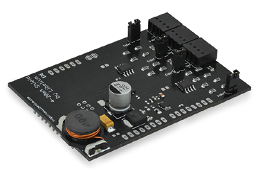
APPLICATIONS
- Sensors and instruments
- Remote transducers
- Monitoring processes
- Data transmission in industrial ambients
SENSORS
- Type: Analog
- Media: Twisted Pair
- No. of devices: 4
- Distance: 900m
- Supply: 12 V
The user can choose among a wide variety of standard sensors
PROTOTYPING SENSOR
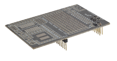
APPLICATIONS
- Prepared for the integration of any kind of sensor.
SENSORS
- Pad Area
- Integrated Circuit Area
- Analog-to-Digital Converter (16b)
It is possible to find more detailed information in the manual for each board at: https://development.libelium.com/waspmote/
{warning.fa-dot} Remember that damages caused by external agents (animals, fire, flooding, gases, etc) are not covered under the Warranty. High concentration of corrosive gases (for example, NH3 -ammonia-, present in pig farms due to swine manure), causes early degradation of the devices, especially the most sensitive or exposed ones, such as sensors.
Power
In the sensor connector there are also several power pins, specifically GND, 3.3 V and 5 V.
- 3V3 SENSOR POWER: 3.3 V power voltage (200 mA maximum) which is controlled from the Waspmote execution code.
- 5V SENSOR POWER: 5 V power voltage (200 mA maximum) which is controlled from the Waspmote execution code.