- Hardware description
- Power and time consumption
- User switches
- Reset button
- Node setup
- How the node works
- Node parameters
Smart Parking node
Hardware description
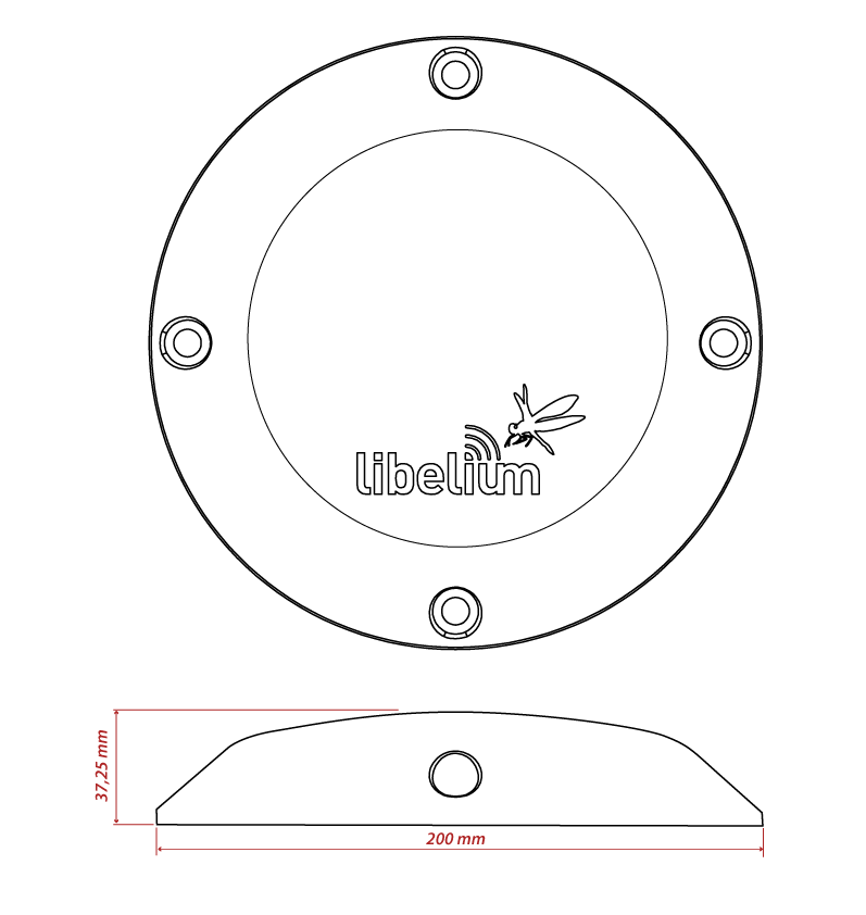
The Smart Parking node is based on 2 different pieces: the base and the external enclosure. The base of the Smart Parking node includes the PCB, the battery, the antenna and the internal enclosure piece. The base is screwed to the external enclosure piece.
The next table shows the basic Smart Parking node characteristics.
| Enclosure dimensions | 200 x 200 x 37.25 mm |
| Enclosure materials | Polyamide, polypropylene and glass fiber |
| Weight | 0.813 kg (including installation accessories) 0.540 kg (just the Smart Parking node) |
| Power supply | Built-in lithium-thionyl chloride (Li-SOCl2) batteries; expected lifetime of 4-10 years* |
| Configurable sleep time | Min: 10 s / max: 10 min |
| Radio protocol | LoRaWAN module |
| Dual detection | Radar (main) and magnetic (backup) |
| Provisioning | Ready to install (factory LoRaWAN OTAA IDs and key are pre-configured to each node) |
| Node configuration | Via Libelium Cloud |
| LoRaWAN configuration | Via "Smart Devices App" (Java desktop application) |
| Operating temperature | -20 to +65 °C |
| Market certifications | CE (Europe) FCC (USA) UKCA |
| Ingress protection certification | IP68 (maximum rating against dust and water ingress) |
| Impact protection certification | IK10 (maximum rating against impacts) |
(*) Under normal circumstances and depending on settings
(**) Continuous operation in extreme temperatures (high or low) is not recommended for long periods of time – for example, this may lead to reduced battery capacity, lower radar performance or random resets
The radar sensor performs a re-calibration process periodically to deliver the most accurate measurement. It is an automatic feature, so no user action is required. Besides, this re-calibration is internal, meaning it is always completed correctly, regardless of whether there is a vehicle above the node or not.
Node versions
Libelium provides the next versions of Smart Parking:
| Reference | Version | Operating frequency |
|---|---|---|
| SP-EU | Smart Parking EU | 863.0 to 870.0 MHz (LoRaWAN EU863-870) |
| SP-US | Smart Parking US | 902.0 to 928.0 MHz (LoRaWAN US902-928) |
| SP-APLA-AU | Smart Parking APAC/LATAM/AU/AU915 | 915.2 to 927.8 MHz (LoRaWAN AU915-928) |
| SP-IN | Smart Parking IN | 865.0 to 867.0 MHz (LoRaWAN IN865-867) |
| SP-APLA-AS | Smart Parking APAC/LATAM/AU/AS923 | 923 MHz (LoRaWAN AS923) |
Firmware versions
Firmware versions of Smart Parking nodes:
| Firmware version | Description |
|---|---|
| v1.0.x | First Smart Parking node versions (deprecated) |
| v1.1.1 | First stable release in v1.1.x generation |
| v1.1.2 | Minimum sleep time from 20 to 10 seconds |
| v1.1.3 | Fixed LoRaWAN US manufacturer issues |
| v1.1.4 | Improved sensor measurement with high temperatures |
| v1.2.0 | Improved power consumption in bad coverage behaviour and doubtful states. Update in frame header: re-calibration bit to doubtful detection |
LoRaWAN regions
The Smart Parking node supports the next LoRaWAN regions:
| LoRaWAN region | Supported by |
|---|---|
| EU 863-870 MHz ISM Band (Europe) | Smart Parking EU |
| US 902-928 MHz ISM Band (United States) | Smart Parking US |
| AU 915-928 MHz ISM Band (Australia) | Smart Parking APAC / LATAM / AU / AU915 |
| IN 865-867 MHz ISM Band (India) | Smart Parking IN |
| AS 923 MHz ISM Band (Asia and ASEAN region) | Smart Parking APAC / LATAM / AU / AS923 |
| CN 779-787 MHz ISM Band (China) | Not available |
| CN 470-510 MHz ISM Band (China) | Not available |
| KR 920-923 MHz ISM Band (South Korea) | Not available |
| 433 MHz ISM Band (Worldwide) | Not available |
If you are interested in further information about LoRaWAN country regulations, please refer to the LoRa Alliance regional parameters document.
LoRaWAN protocol and parameters
LoRaWAN is a Low Power Wide Area Network (LPWAN) protocol. It is a spread-spectrum modulation technique at extremely low data-rates which permits sending data achieving long ranges.
The most important LoRaWAN parameters are:
- LoRaWAN EUI: Read-only, 8-byte, unique identifier which defines each LoRaWAN module in the market.
- Device EUI: Read/write, 8-byte identifier configured into the LoRaWAN module to be used as operating identifier. By default, the "LoRaWAN EUI" of the module is factory-configured as "Device EUI" in the Smart Parking node.
- Join mode: ABP or OTAA. Defines how the module joins the network. Different keys are needed for each method.
- Device address: Needed for ABP. The 4-byte address of the the LoRaWAN module. Must be unique in its own sub-network.
- Network Session Key: Needed for ABP. The 16-byte AES key. Used to generate Message Integrity Check.
- Application Session Key: Needed for ABP. The 16-byte AES key. Used to encrypt data.
- Application EUI: Needed for OTAA. The 8-byte application identifier. Needed for opening an OTAA session and exchange encryption keys.
- Application Key: Needed for OTAA. The 16-byte key. Needed for opening an OTAA session and exchange encryption keys.
- Data-rate: Defines the transmission rate (bits per second). Each data-rate settings combines different Spreading Factor (SF) and bandwidth (BW). By default, all LoRaWAN regions use the same data-rate (DR 0). However, depending on the region, that means different SF and BW:
- LoRaWAN EU863-870 version: SF12 / 125 kHz
- LoRaWAN IN865-867 version: SF12 / 125 kHz
- LoRaWAN AS923 version: SF12 / 125 kHz
- LoRaWAN US902-928 version: SF10 / 125 kHz
- LoRaWAN AU915-928 version: SF10 / 125 kHz
- ADR: Adaptive Data Rate setting which can be enabled or disabled. If ADR is enabled, the server will optimize the data-rate based on the information collected from the network: the RSSI / SNR of the last received packets.
If you are interested in further information about LoRaWAN specifications, please refer to the LoRa Alliance specifications document.
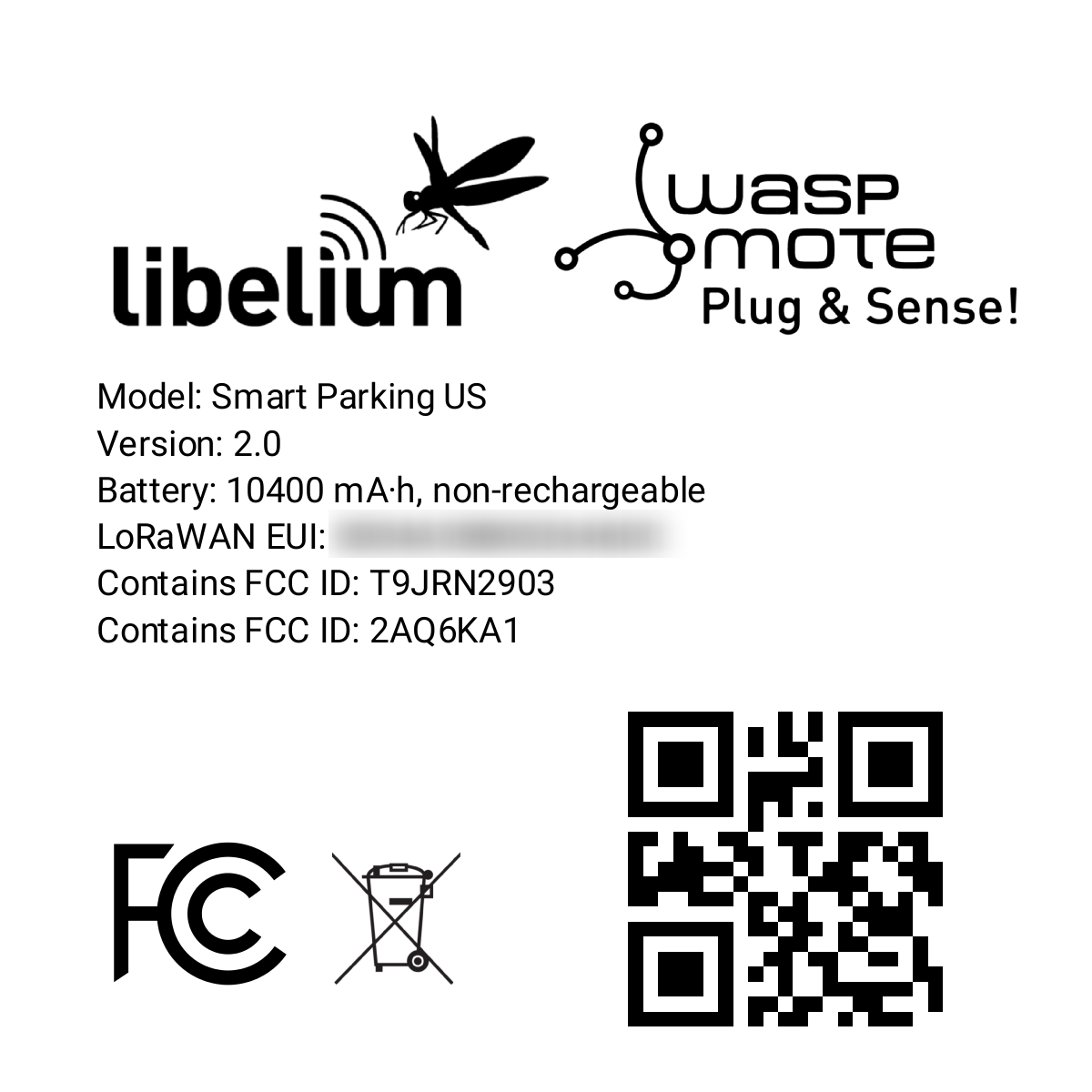
Identification label
There is a sticker on the bottom side of the Smart Parking node base. In this sticker, several device specifications can be seen. For example the "Model" which refers to the device's region. Also, the unique "LoRaWAN EUI" is displayed so each node can be distinguished.
Power and time consumption
The Smart Parking node firmware executes different steps since the node is started. Firstly, the node's setup and then an infinite loop where every cycle is based on measuring, sending if needed and sleeping. The next tables show the power and time consumption of each step modelled as a pulse of a specific time duration and average power consumption.
Smart Parking EU
| Power consumption | Time consumption | |
|---|---|---|
| Node setup | 22.9 mA | 59 s |
| Measure cycle | 26 mA | 340 ms |
| Measure and send cycle | 17 mA | 6 s |
| Sleep cycle | 5.5 uA | Depends on sleep time settings |
(*) LoRaWAN EU is set to the default SF12 settings (worst case). The send process may be lower power if the node is close to the base station.
Smart Parking US
| Power consumption | Time consumption | |
|---|---|---|
| Node setup | 21.8 mA | 53 s |
| Measure cycle | 26 mA | 340 ms |
| Measure and send cycle | 20 mA | 3.6 s |
| Sleep cycle | 5.5 uA | Depends on sleep time settings |
(*) LoRaWAN US is set to the default SF10 settings (worst case). The send process may be lower power if the node is close to the base station.
User switches
The Smart Parking node has 2 switches to manage the working mode:
- On/Off switch: Determines whether the node is powered-on or powered-off
- App/Boot switch: When the node is powered-on, this switch determines the performance state of the device
- App position must be used for a normal operation mode, so the device executes the firmware within it
- Boot position must be used for configuring purposes only
<img src="/images/docs/parking-v2/parking_014.jpg" alt="Smart Parking node "users switches"" style="width:40%;" >
When the node is powered-on (On switch), you can change from App to Boot or viceversa by changing the state of the App/Boot switch. However, you must press the reset button to apply the operation mode change. Another possibility to successfully change the operation mode step-by-step would be to: power down the device (Off switch), change the App/Boot switch, press the reset button and then power on the device.
Never leave the device set to On and Boot for more time than needed. The bootloader does not provide any sleep mode and it will waste the battery of the device. So when you finish reconfiguring the device, please set the node in off state.
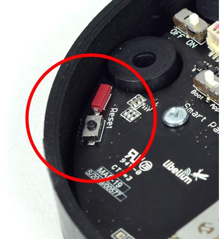
Reset button
The reset button can be used to re-start the node in the corresponding operation mode (App or Boot). If the node is set up to "App" (normal operation mode), pressing the reset button will re-start the program execution. On the other hand, if the node is set up to Boot (configuration mode), pressing the reset button will re-start the MCU bootloader for reconfiguration or firmware update.
Node setup
"Ready to install" state
Libelium provides the nodes "ready to install" so the user only needs to install the nodes and follow the "Magnet start-up" process.
The Smart Parking node has a power-on process in order to put the device into a "ready-to-install" state:
- Step 1: The switches are set to "App" and "Off" (press the reset button to make sure you discharge capacitors)
- Step 2: You power the device on by sliding the switch from "Off" to "On"
- Step 3: Both LEDs (red and green) blink rapidly for 5 times
- Step 4: Red LED blinks once for 1 second to indicate that the device enters sleep mode for the 1st time. Now the node is in a "ready to install" state. The customer should install the node on the real scenario and perform the "Magnet start-up" process.
<img src="/images/docs/parking-v2/parking_018b.jpg" alt=""Ready-to-install" LED indication" style="width:20%;" >
You can see how the previous steps are performed in this video: Ready to install process
How to close the Smart Parking node
After following the previous steps, the device can be closed. In order to close the node correctly and ensure correct sealing, the following steps must be strictly followed.
- Step 1: Make sure that the screws have the o-rings to prevent water ingress.
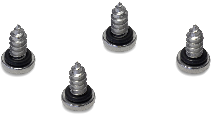
- Step 2: Ensure that the top surface of the gasket is clean and contains no foreign objects.
- Step 3: Place the inner casing inside the outer casing and make sure that the 2 position marks match.
- Step 4: Insert the screws and tighten them halfway.
- Step 5: Finally, tighten the 4 screws firmly. Do not use the maximum pressure (do not go all the way with the screws), because the o-rings could be ejected from the screws, and then the waterproof feature would NOT be valid. Besides, do not screw too hard and keep on screwing, because the screws could carve the female sockets, expanding their inner diameter; this would cancel the waterproof quality too.
Libelium manufactures and provides all nodes configured after following all explained steps, so the node is "ready to install". By factory default, all nodes are configured with their unique LoRaWAN EUI and random private keys. On the other hand, if different LoRaWAN parameters are desired, “SmartDevicesApp” must be used to change the settings and repeat the previously explained steps.
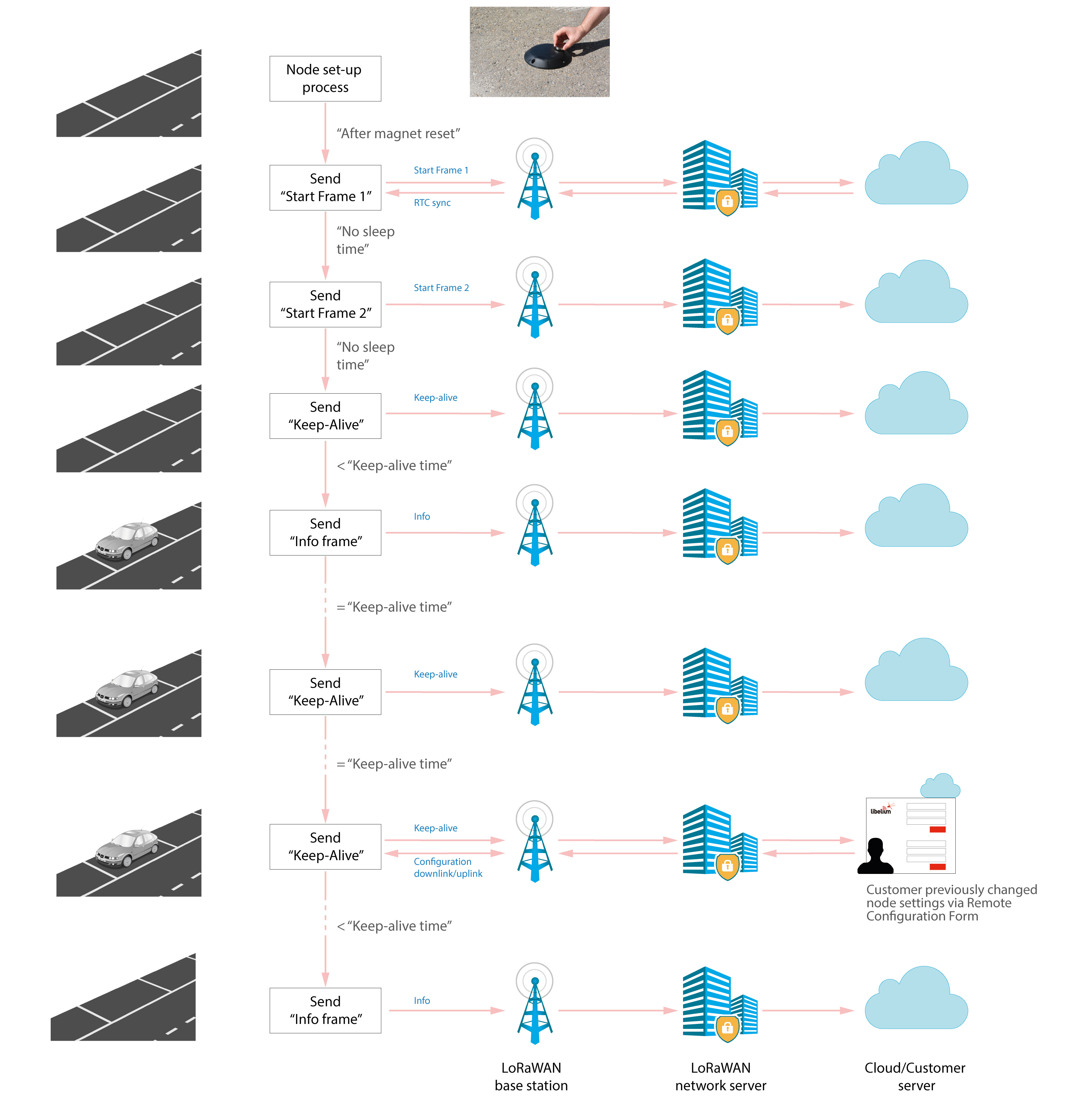
"Magnet start-up" process
Once the node has been set to "ready to install" state and it has been closed and placed on the parking slot, the "magnet start-up" must be done. This process consists on resetting the device using the magnet for 3 consecutive times. Each magnet reset must be separated by at least one second period.
The best way to proceed with the magnet is to go over the enclosure from left to right in a one-motion movement. Then wait for at least one second (although you can wait more) and proceed again until you complete 3 magnet resets.
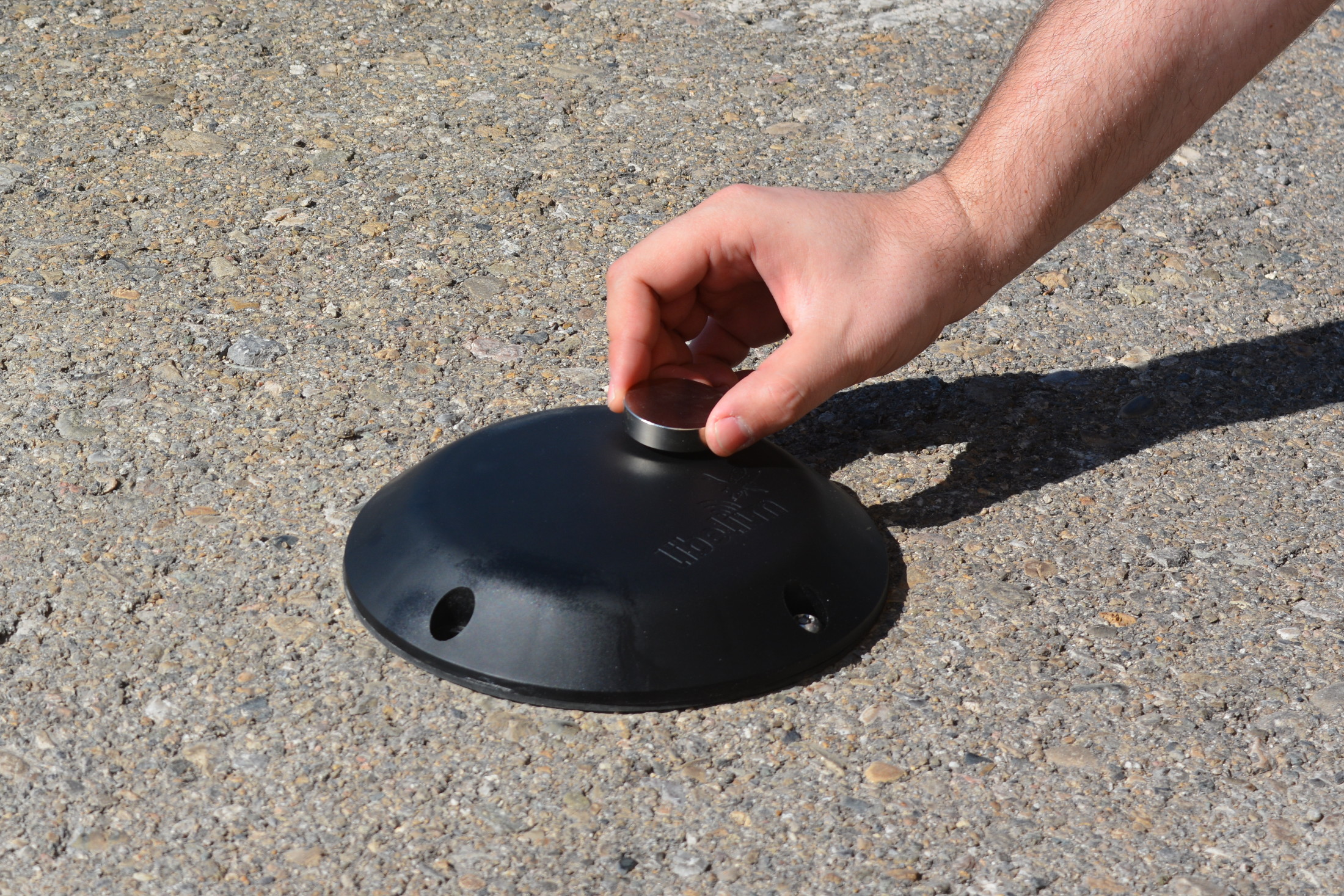
In the next video-clip you can see how the "magnet start-up" is performed: Magnet start-up
After finishing the "magnet start-up", the node starts working normally for the rest of the time. No more three-time "magnet resets" are needed in order to reset the device properly. So if a 4th magnet reset or software reset is applied, the device will reset and continue working normally again.
The "magnet start-up" is only mandatory when the node is powered from a power-off state. In other words, when the device is set to a "ready to install" state.
How the node works
Frame types
The Smart Parking architecture manages different uplink and downlink frames. The next table shows the uplink frames:
| Frame type | Description |
|---|---|
| Start frame 1 | First frame sent by the node when starting (with params settings) |
| Start frame 2 | Second frame sent by the node when starting (with params settings) |
| Info frame | Used to inform a Parking Status change |
| Keep-alive frame | Used to inform the device keeps working since last reported status |
| Configuration uplink | Used to confirm a "Configuration downlink" was applied or not |
| RTC update request | Used to request for an RTC sync once every day |
The next table shows the downlink frames:
| Frame type | Description |
|---|---|
| Configuration downlink | Used to update the node parameters. After the customer sets up a new node configuration in the Remote Configuration Form a new "Configuration downlink" frame is enqueued into the LoRaWAN network server's downlink queue. |
| RTC sync frame | Used to sync the node's RTC to the server's timestamp. It is the mandatory response to "Start frame 1" and "RTC update request" uplink frames. |
The uplink frames are 11-byte long to always comply with the LoRaWAN datarate worst case scenario. Their structure consists on 2 parts: header and payload. The "header" format is always the same for all uplink frame types. On the other hand, the "payload" format may be different for each frame type.
Regarding the downlink frames, they have variable length and its format is private to the customer. The "RTC sync frame" is the mandatory response for both "Start Frame 1" and "RTC update request" frames. The "RTC sync frame" provides the server time to the nodes in order to keep the RTC updated. Also, the "Configuration downlink" is an asynchronous frame sent by the server when the Remote Configuration Form is managed by the customer.
You must keep in mind that when a downlink packet is requested there are usually some issues related to LoRaWAN network latency. This implies that the 1st request attempt usually fails. In that case, a 2nd attempt is sent in order to retrieve the lost downlink packet. For this reason, you might see that a couple of "Start Frame 1" or "RTC update request" frames are sent sequentially during the execution of the program.
Libelium Cloud has the needed code to parse data inside frames into a more comprehensive structure. The cloud connectors also provide the needed tools to transmit the parsed data to a 3rd party IoT cloud.
Node program execution
Node parameters
Parameters description and ranges
The Smart Parking node has different parameters that change the timing and detection performance of the node. The next table shows the node parameters:
| Parameter | Range | Description |
|---|---|---|
| Sleep time | 1-10 min or 10-59 s | Minutes or seconds elapsed between each measurement cycle |
| Keep-alive time | 0.5, 1, 2,..., 23 hour | Hours elapsed since last uplink message which triggers a new Keep-alive frame |
| Night-mode | 0 or 1 | Night-mode disabled/enabled |
| Night-mode start | 0, 1,..., 23 hour | Night-mode starts when RTC reaches this parameter field |
| Night-mode duration | 1, 2,..., 15 hour | Night-mode period is equal to this field |
| Night-mode sleep | 1, 2,..., 10 min | Sleep time applied during night-mode |
| Radar range start | 20 to 50 cm | Starting measurement distance (objects below this value are not detected) |
| Radar range length | 50 to 100 cm | Range of measurement to be added to "range start" value |
| Radar threshold | 10 to 50 | Threshold used in detection algorithm, so higher threshold imply less sensitive detection |
| LoRaWAN join mode | 0 (ABP) or 1 (OTAA) | Join mode used by the LoRaWAN radio module |
| LoRaWAN DevEUI | 8-byte identifier | Defines the device EUI used by the LoRaWAN radio |
| LoRaWAN DevAddr | 4-byte identifier | Defines the device address used by the LoRaWAN radio in ABP mode |
| LoRaWAN NwkSKey | 16-byte key | Defines the LoRaWAN Network Session Key used by the LoRaWAN radio in ABP mode |
| LoRaWAN AppSKey | 16-byte key | Defines the LoRaWAN Application Session Key used by the LoRaWAN radio in ABP mode |
| LoRaWAN AppKey | 16-byte key | Defines the LoRaWAN Application Key used by the LoRaWAN radio in OTAA mode |
| LoRaWAN AppEUI | 8-byte identifier | Defines the LoRaWAN Application EUI used by the LoRaWAN radio in OTAA mode |
| LoRaWAN port | 1 to 223 | Defines the port used for uplink sendings |
| LoRaWAN ADR | 0 (off) or 1 (on) | Defines if Adaptive Data Rate is enabled or disabled |
| LoRaWAN RX1 Delay | 0 to 65536 | Defines the delay after first LoRaWAN rx window |
| LoRaWAN Subband | 8-bit bitmap | Defines the sub-band used by the LoRaWAN radio (only applies to US and AU versions) |
The LoRaWAN identifiers and keys must be registered in the LoRaWAN network server before starting the node in order to receive data. For OTAA mode: DevEUI, AppEUI and Appkey. For ABP mode: DevEUI, DevAddr, NwkSKey and AppSKey.
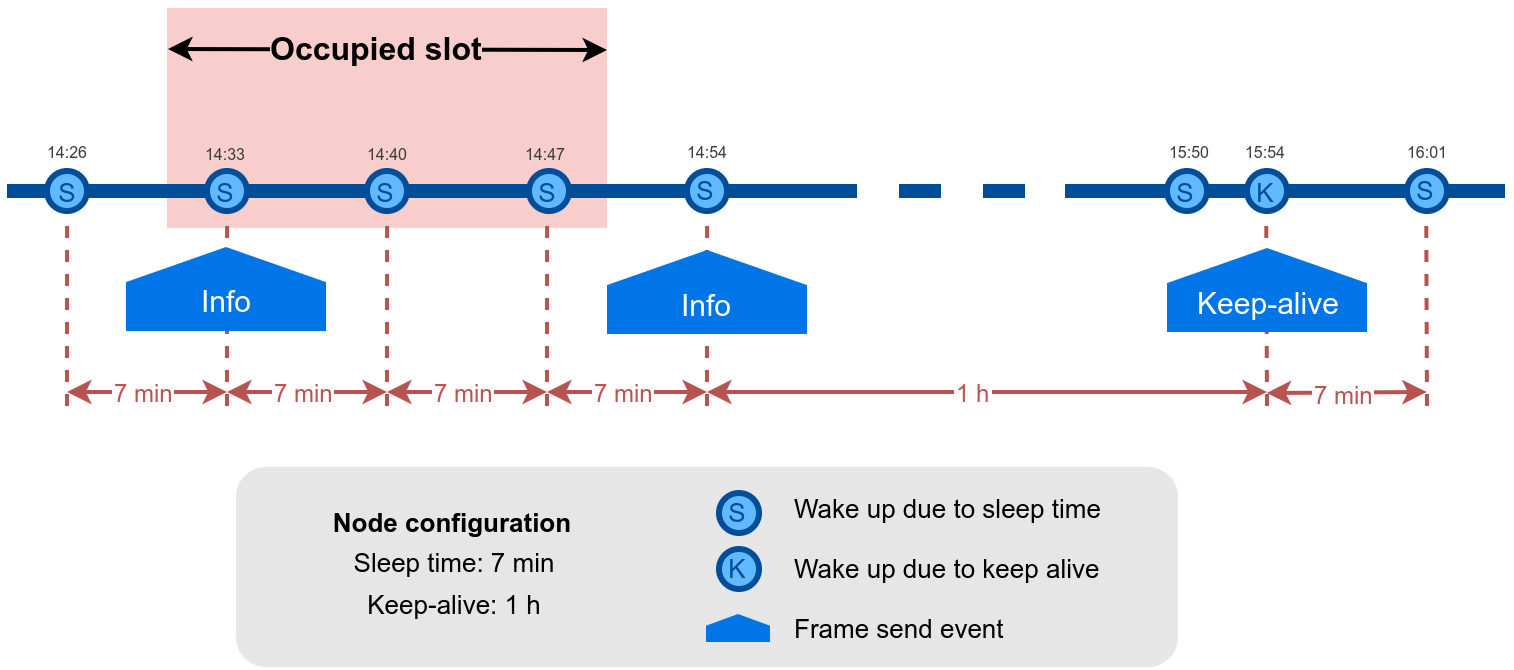
Understanding Info and Keep-alive frames
In the regular working mode (day-mode), "Sleep" and "Keep-alive" parameters are used. So the node normally sleeps for a specific "Sleep" time then wakes-up, measures and applies the algorithm detection in order to detect changes in the parking slot.
If a change is detected from 'free' to 'occupied' or viceversa, then an "Info" frame is sent. If no change occurred during the last "Keep-alive" time, then a Keep-alive frame is sent. Besides, if a sensor error is detected, a Keep-alive frame sending is forced in order to inform about this issue.
Example parameters used:
- Sleep: 7 minutes
- Keep-alive: 1 hour
Understanding night-mode
As shown in the parameters table, there are some parameters that allow the user to configure the node to use 2 working modes depending on time settings: day-mode and night-mode.
The night-mode is a secondary and optional working mode that allows the user to configure a different time basis parameters in order to reduce the battery impact. So, it was developed to use it when the parking slot is expected to have fewer changes (i.e. at night). Therefore, a different night-mode "Sleep" setting is used.
It is not mandatory to use the night-mode during night. This mode is thought to be used when less vehicle movement is expected in the parking slots. Which could be during day time.
Example:
-
Day-mode:
- Sleep: 1 minute
-
Night-mode:
- Night-mode start hour: 21 hours (9 PM)
- Night-mode duration: 10 hours (Night-mode goes from 9 PM to 7 AM)
- Night-mode sleep time: 10 minutes
In the example, from 9 PM to 7 AM, the node will waste less battery because measurements are done every 10 minutes instead every minute. Keep-alive events are not shown but a Keep-alive event would be triggered if no change occurs in the parking slot.
.png>)
The conclusion is that the Night-mode is interesting for customers who certainly know the parking slot is expected to have fewer changes during large periods of time every day.
From October 2019 the "keep-alive night-mode" setting was deprecated to simplify the parameter management. Since then, there is a single keep-alive setting, for both "normal mode" and "night mode".
Understanding RTC synchronization
There are specific frame types that allow the node to synchronize the RTC to the server timestamp.
The "Start Frame 1" expects an answer from the server with the timestamp (hours and minutes). This frame is sent after starting the node or a software reset.
Besides, the node's firmware provides a mechanism which an "RTC update request" frame is sent every 24 hours since the node was started or reset. This frame waits for a downlink frame which brings the current server timestamp (hour and minutes).
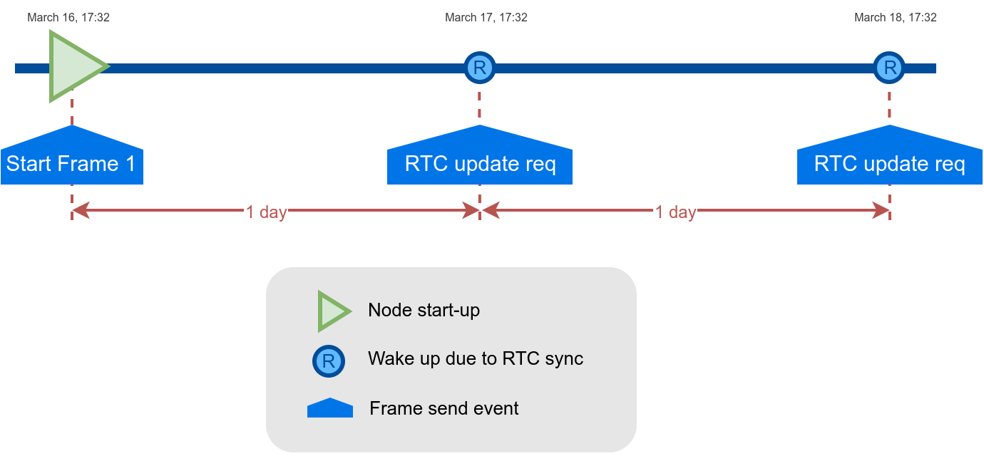
The RTC sync is important for Night-mode only where it mandatory to operate with a correct timestamp in order to enter and exit from night-mode to day-mode and viceversa.
Understanding uplink frames format (real example)
The next table shows all frames sent by a single node since it was started. The different columns display the parsed data from the received "uplink data".
Example:
-
Day-mode:
- Sleep: 1 minute
- Keep-alive: 2 hour
-
Night-mode:
- Night-mode start hour: 22 hours (10 PM)
- Night-mode duration: 8 hours (Night-mode goes from 10 PM to 6 AM)
- Night-mode sleep time: 5 minutes
It is possible to distinguish the starting frames at the beginning of the execution. Then the node informs with a new Keep-alive every 2 hours. Any change of Parking slot status implies a new Info frame. And after 24 hours working, you can see the RTC request performed by the node.
| Timestamp | F. Type | Parking lot | Battery | Seq |
|---|---|---|---|---|
| 04/15/19 15:59 | 4 (Start 1) | Not available | 0 | 0 |
| 04/15/19 15:59 | 5 (Start 2) | Not available | 0 | 1 |
| 04/15/19 15:59 | 1 (Keep-alive) | Free | 0 | 2 |
| 04/15/19 17:29 | 1 (Keep-alive) | Free | 0 | 3 |
| 04/15/19 19:29 | 1 (Keep-alive) | Free | 0 | 4 |
| 04/15/19 21:29 | 1 (Keep-alive) | Free | 0 | 5 |
| 04/16/19 23:29 | 1 (Keep-alive) | Free | 0 | 6 |
| 04/16/19 01:29 | 1 (Keep-alive) | Free | 0 | 7 |
| 04/16/19 03:29 | 1 (Keep-alive) | Free | 0 | 8 |
| 04/16/19 05:29 | 1 (Keep-alive) | Free | 0 | 9 |
| 04/16/19 06:04 | 0 (Info) | Occupied | 0 | 10 |
| 04/16/19 08:04 | 1 (Keep-alive) | Occupied | 0 | 11 |
| 04/16/19 10:04 | 1 (Keep-alive) | Occupied | 0 | 12 |
| 04/16/19 12:04 | 1 (Keep-alive) | Occupied | 0 | 13 |
| 04/16/19 14:05 | 1 (Keep-alive) | Occupied | 0 | 14 |
| 04/16/19 15:58 | 7 (RTC request) | Occupied | 0 | 15 |
| 04/16/19 15:59 | 7 (RTC request) | Occupied | 0 | 16 |
| 04/16/19 17:59 | 1 (Keep-alive) | Occupied | 0 | 17 |
| 04/16/19 18:32 | 0 (Info) | 0 | 0 | 18 |
| 04/16/19 20:02 | 1 (Keep-alive) | 0 | 0 | 19 |
| 04/16/19 22:32 | 1 (Keep-alive) | 0 | 0 | 20 |
| 04/17/19 00:02 | 1 (Keep-alive) | 0 | 0 | 21 |
Factory default values
Libelium provides all Smart Parking nodes with factory default parameters.
| Parameter | Default value |
|---|---|
| Sleep time | 1 min |
| Keep-alive time | 2 hour |
| Night-mode | 0 (disabled) |
| Night-mode start | 0 hour |
| Night-mode duration | 6 hour |
| Night-mode sleep | 5 min |
| Radar range start | 20 cm (should not be changed) |
| Radar range length | 60 cm (should not be changed) |
| Radar threshold | 30 (should not be changed) |
| LoRaWAN join mode | 1 (OTAA) |
| LoRaWAN DevEUI | unique factory default value |
| LoRaWAN DevAddr, | unique factory default value |
| LoRaWAN NwkSKey | unique factory default value |
| LoRaWAN AppSKey | unique factory default value |
| LoRaWAN AppKey | unique factory default value |
| LoRaWAN AppEUI | unique factory default value |
| LoRaWAN port | 3 |
| LoRaWAN ADR | 0 (off) |
| LoRaWAN RX1 Delay | 1000 (should not be changed) |
| LoRaWAN Subband | 8-bit bitmap |
Configure new parameter values
Both Smart Devices App and Libelium Cloud allow the user to update program parameters to the node:
- Smart Devices App: it is a desktop Java application which implies opening the node enclosure and plug a micro-USB cable to the node (the new configuration is flashed to the node's memory via the USB cable).
- Libelium Cloud: permits to remotely change some of the node parameters.
Regarding the time and sensor parameters, the same values are set to all nodes manufactured by Libelium. The default values can be seen in the previous section. However, the customer can configure the time and sensor settings using both Smart Devices App and Remote Configuration Form.
Regarding the LoRaWAN parameters, all keys are randomly generated for each node and kept secret. The DevEUI set to the node is the LoRaWAN hardcoded EUI which is unique for each radio chipset. However, the client can configure/modify all LoRaWAN parameters using the Smart Devices App only (the Remote Configuration Form does not permit it).
For further information about this matter please refer to the "Smart Devices App" section.