Wireless Sensor Networks
Meshlium and Waspmote
One of the main applications of Meshlium is being a gateway for Wireless Sensor Networks based on Waspmote and Plug & Sense! devices. These are sensor nodes that can work with different communication technologies like WiFi, 4G or XBee among others. More than 70 sensors are already available and a complete open source IDE (API libraries + compiler) make really easy to start working with the platform.
More info at:
{% embed url="https://development.libelium.com/waspmote/" caption="" %}
{% embed url="https://development.libelium.com/plug-and-sense/" caption="" %}
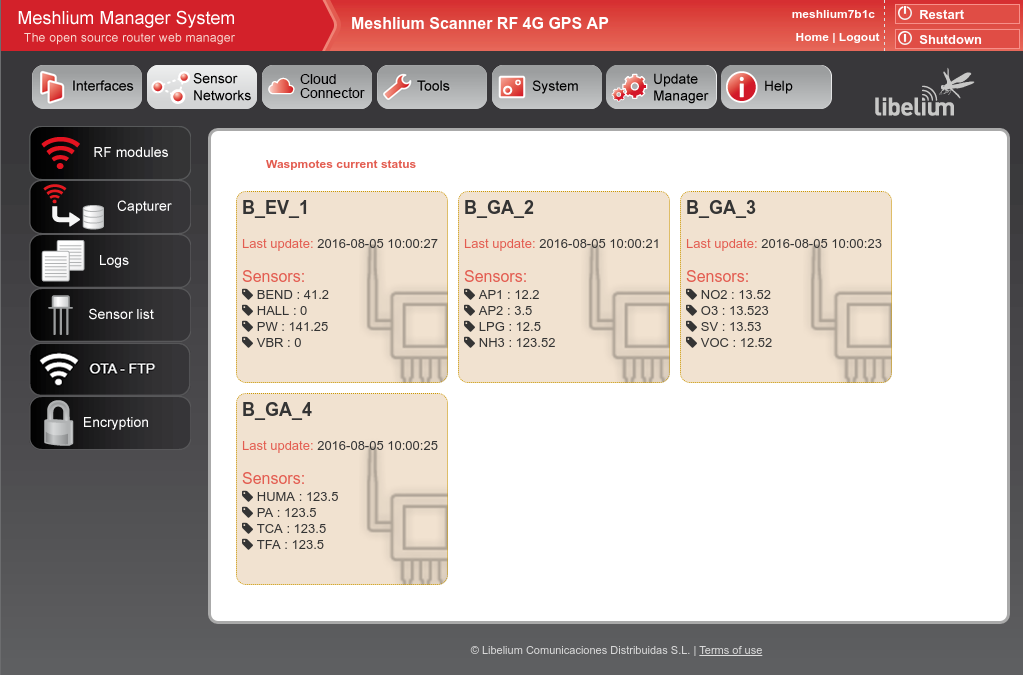
In the main page of Sensor Networks tab will be shown the devices in the system showing the last received data.
Receiving and storing data
Receiving trough RF communications
RF module setup
Meshlium can integrate 3 different RF modules: XBee-PRO 802.15.4 (2.4 GHz), XBee 868LP (868 MHz) and XBee-PRO 900HP (900 MHz). It can have up to 2 RF modules at the same time.
RF modules setup can be found in:
Sensor Networks -> RF modules
The plugin will show:
- one tab for each module detected in the device.
- switch button to enable/disable the sensor parser service.
- menu for changing logging levels in HTTP and RF parser.

XBee-PRO 802.15.4 radio setup
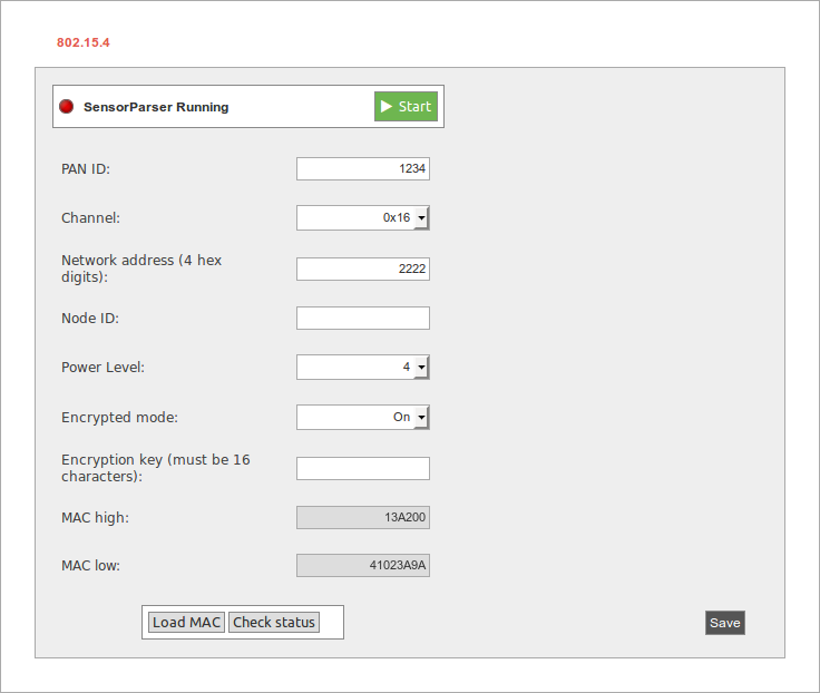
In this module the parameters to setup are:
- PAN ID: Personal Area Network ID (also known as Network ID). It is the identifier of the network. It has to be the same in all the nodes in order to be able to send data to this Meshlium.
- Channel: Frequency channel used for transmissions.
- Network Address: User defined identifier for the node in the network. 4 hexadecimal digits (MY).
- Node ID: readable name set for the device, by default "Meshlium". Up to 20 characters.
- Power level: [0-4] By default 4.
- Encrypted mode: Internal XBee AES 128 bits encryption. Disabled by default.
- Encryption key: 16 characters.
- MAC: 64 bits hardware address of the module. It is a read-only value divided in two parts:
- MAC-high: 32 bits (8 hexadecimal digits).
- MAC-low: 32 bits (8 hexadecimal digits).
This setup must be consistent with those set on the Waspmote and Plug and Sense nodes.
In the bottom part of the interface, the button "Check status" allows to check if the module setup is concordant with values shown in the interface. The button "Save" will write the parameters in the module.
Both process ("Save" and "Check status") require the sensorParser daemon to be stopped. This means no frames will be received while executing this actions. Be patient this can take up to 1 minute to finish.
XBee 868LP radio setup
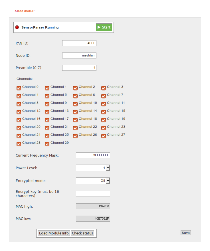
In this module the parameters to setup are:
- PAN ID: Personal Area Network ID (also known as Network ID). It is the identifier of the network. It has to be the same in all the nodes in order to be able to send data to this Meshlium.
- Node ID: readable name set for the device, by default "Meshlium". Up to 20 characters.
- Preamble: An extension to PAN ID. It needs to be the same in the nodes too.
- Channel: This module allow to select the channels that can be used. The module automatically selects the channel for the communication between available ones. Once the channels are selected, the plugin generates the "Channel Frequency Mask" (read-only 8 hex digits) that the needs to be set in the nodes.
- Power level: [0-4] By default 4.
- Encrypted mode: Internal XBee AES 128 bits encryption. Disabled by default.
- Encryption key: 16 characters.
- MAC: 64 bits hardware address of the module. It is a read-only value divided in two parts:
- MAC-high: 32 bits (8 hexadecimal digits).
- MAC-low: 32 bits (8 hexadecimal digits).
XBee-PRO 900HP radio setup
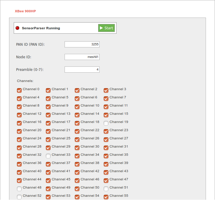
PAN ID: Personal Area Network ID (also known as Network ID). It is the identifier of the network. It has to be the same in all the nodes in order to be able to send data to this Meshlium.
Node ID: readable name set for the device, by default "Meshlium". Up to 20 characters.
Preamble: An extension to PAN ID. It needs to be the same in the nodes too.
Channel: This module allow to select the channels that can be used. The module automatically selects the channel for the communication between available ones. Once the channels are selected, the plugin generates the "Channel Frequency Mask" (read-only 8 hex digits) that the needs to be set in the nodes.
Power level: [0-4] By default 4.
Encrypted mode: Internal XBee AES 128 bits encryption. Disabled by default.
Encryption key: 16 characters.
MAC: 64 bits hardware address of the module. It is a read-only value divided in two parts:
MAC-high: 32 bits (8 hexadecimal digits).
MAC-low: 32 bits (8 hexadecimal digits).
In this module the parameters to setup are:
- PAN ID: Personal Area Network ID (also known as Network ID). It is the identifier of the network. It has to be the same in all the nodes in order to be able to send data to this Meshlium.
- Node ID: readable name set for the device, by default "Meshlium". Up to 20 characters.
- Preamble: An extension to PAN ID. It needs to be the same in the nodes too.
- Channel: This module allow to select the channels that can be used. The module automatically selects the channel for the communication between available ones. Once the channels are selected, the plugin generates the "Channel Frequency Mask" (read-only 16 hex digits) that the needs to be set in the nodes. In the bottom part of the interface is shown the minimum number of channels that have to be selected.
- Power level: [0-4] By default 4.
- Encrypted mode: Internal XBee AES 128 bits encryption. Disabled by default.
- Encryption key: 16 characters.
- MAC: 64 bits hardware address of the module. It is a read-only value divided in two parts:
- MAC-high: 32 bits (8 hexadecimal digits).
- MAC-low: 32 bits (8 hexadecimal digits).
Encryption setup
Link layer key management (AES-128)
This feature is provided by XBee modules.
Encryption is this layer provided through the AES algorithm. Specifically through the type AES-CTR. In this case the Frame Counter field has a unique ID and encrypts all the information contained in the Payload field which is the place in the link layer frame where the data to be sent is stored. The way in which the libraries have been developed for module programming means that encryption activation is as simple as running the initialization function and giving it a key to use in the encryption.
{
    xbee.encryptionMode(1);
    xbee.setLinkKey(key);
}
In the Manager System, on Sensor Network section, users can encrypt messages on link layer. It can be achieved by setting the parameters:
- Encrypted mode: true/false (by default false).
- Encryption Key: Must be 16/24/32 characters depending on the AES encryption type (128/192/256 bits).
See section "RF module setup" for more details about setting encryption.
Application layer key management
Meshlium is capable to properly receive encrypted data from Waspmote. The coding process is made in the application layer, so it is Waspmote and Meshlium processor and not XBee module who encrypts and decrypts the messages.
The user have to set a key for the encryption in Waspmote and Meshlium.
In the Manager System, the menu for managing the encryption options is found in: Sensor Networks -> Encryption
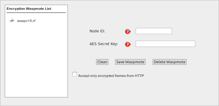
For each Waspmote unit which is able to send frames to Meshlium, Waspmote keys can be added to an encryption Key file. In this interface the user must specify the node ID and the Waspmote AES secret key (128, 192 or 256 bits).
After defining the above fields, press the button "Add Waspmote". A new entry will be generated in the left side list.
For deleting a specific Waspmote unit from the list, select the Waspmote unit and press "Delete Waspmote". The encrypted frames received from this node will not be able to be decrypted anymore.
The option "Accept only encrypted frames from HTTP" is also available. Select this option if you want to discard all the not encrypted frames received by the HTTP parser.
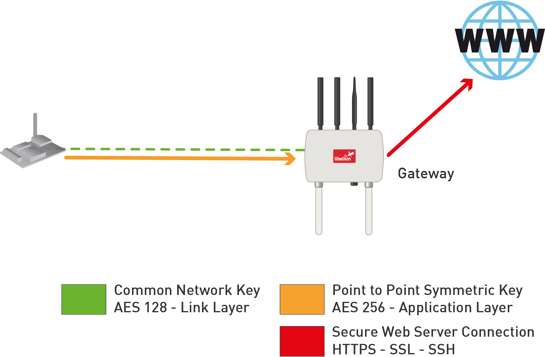
Once the user has properly set the AES keys associated to every Waspmote unit, receiving AES encrypted frames in Meshlium is a straightforward process.
As an encrypted frame arrives to Meshlium, sensorParser program takes the appropriate key for the Waspmote ID. The frame is decoded with the key and the information is extracted to the sensor database.
Bear in mind that to use this feature, the frame have to be created with the Waspmote libraries for AES frames. You can see further information about this in the Waspmote guides.
https://development.libelium.com/waspmote/
Capturing and storing sensor data from RF module
Meshlium will receive the sensor data sent by Waspmote and Plug and Sense using the RF radio and it will store the frames in the local database. Data is stored with the timestamp of the reception in the Meshlium unit. The timestamp is always stored in UTC to avoid inconsistencies (regardless of the time zone selected in Meshlium).
That can be done in an automatic way thanks to the Sensor Parser.
The Sensor Parser is a software system which is able to do the following tasks in an easy and transparent way:
- receive frames from XBee modules (with the Data Frame format).
- parse these frames.
- store the data in the local database.
Besides, the user can add his own sensors, and the data will be parsed in the database too. In order to add your own sensor frames properly go to the section "Sensor list".
We can perform two different storage options with the frames captured:
- Local database.
- External database.
All the data is stored in the local database in the first place, then it can be synchronized to an external database as per user needs.
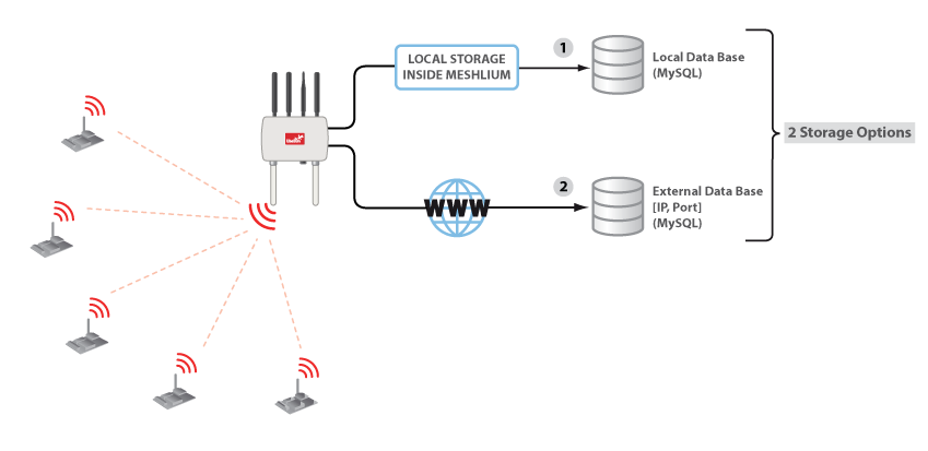
The data stored can be synchronized too to external services using the Internet connection.
Receiving trough 4G / WiFi / Ethernet (HTTP)
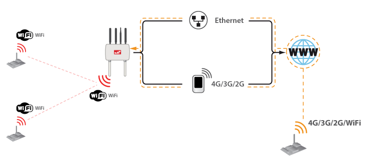
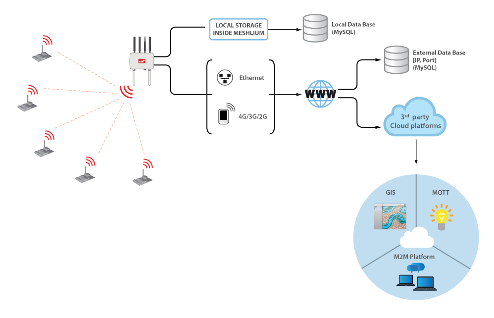
Meshlium accepts POST and GET requests in any of its interfaces so Waspmotes are capable of sending frames, through GPRS, 3G, 4G or WiFi modules, via HTTP requests. Meshlium, through HTTP requests is capable of:
- receive frames from 4G/3G/GPRS/GSM, WiFi or Ethernet via HTTP.
- parse these frames.
- store the data in local Database.
- synchronize the local Database with an external database.
Frames received by this method are stored the same way that RF frames, and are identically processed at synchronization stage.
No configuration of any kind is needed to use HTTP. If HTTPS is needed, certificate configuration would be needed in many cases (self signed certificate is included with Meshlium).
Like the case of RF modules reception, the user can add his own sensors.
Capturer
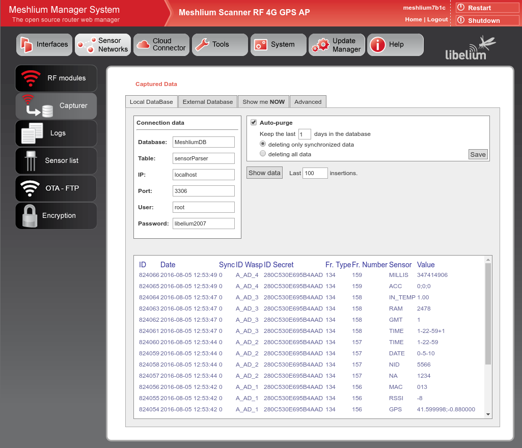
The Capturer plugin is where the user can check most recent data received in order to check if the nodes are sending information.
It can be found in:
Sensor Networks -> Capturer
Capturer plugin have several tabs where the user can see recent data received, manage external database synchronization and perform some local database operations.
Local database
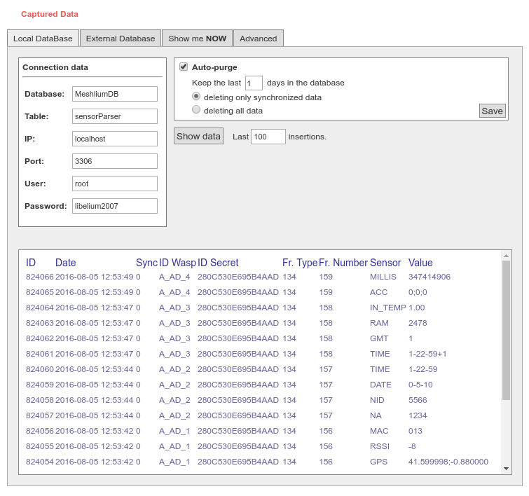
Meshlium has a MySQL database up and running which is used to locally store the information captured. In the "Local Data Base" tab the user can see the default connection parameters.
- Database: MeshliumDB
- Table: sensorParser
- IP: localhost
- Port: 3306
- User: root
- Password: libelium2007
In this tab the user can:
- Show last insertions, up to 500.

- Setup Auto-purge. This function allow to program a daily maintenance in the local database that deletes old data, keeping only the number of days configured, and allowing to delete synchronized data (only external database) or all data.

External Database
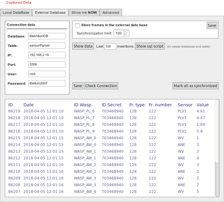
Meshlium can synchronize all the sensor information stored in the local database to an external MySQL database managed by the user.
In this tab the user can:
- Setup the parameters of the external database and check the connection.
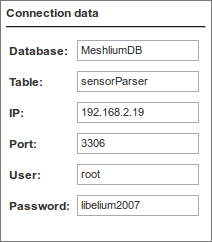
- Enable or disable the synchronization and select the number of fields sent per synchronization iteration.

Show last data inserted in the external database (up to 500 data).

Show the SQL script used to create the database and table needed for the synchronization.

Mark all data in the local database as synchronized so it will not be sent to the external database.

The steps to setup the synchronization are:
- Before configuring anything, make sure you have a MySQL database working under your control. Make sure the database listen to connections in an external IP.
- Press the "Show SQL script" button, copy the SQL code. You can modify user, password, database name and table, as long as you change the setup of the connection to match.
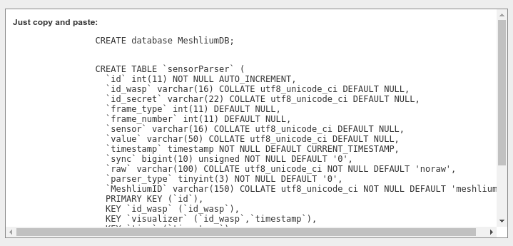
- Enter the connection settings and press "Save" button. You can check the connection now to ensure the settings are correct.
- Enable the service with the checkbox and save.
Before configuring anything, make sure you have a MySQL database working under your control. Make sure the database listen to connections in an external IP.
Press the "Show SQL script" button, copy the SQL code. You can modify user, password, database name and table, as long as you change the setup of the connection to match.
The synchronization service runs every 60 seconds and synchronizes up to 100 data every loop. The service synchronizes first newer data, as it is more relevant for decision making. This could make data in external database to be out of order. As every data has a timestamp, this should not be a problem for using the data in any external application.
Show me Now
In this tab the user can show the last frame received. The user can show only last frame or can specify if the information will be updated periodically with the defined interval just checking the "Use the Defined Interval" button.
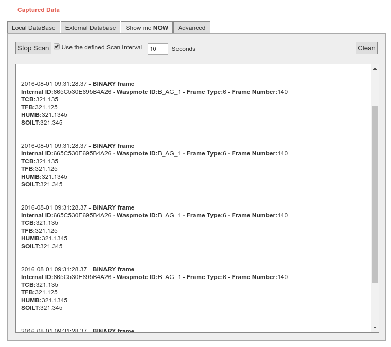
The screen can be cleaned with the button in the top right.
Advanced database options
This tab shows information about local database.
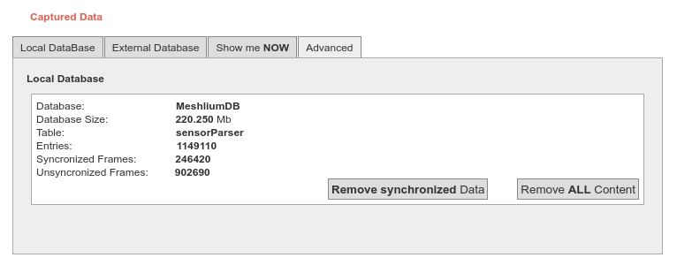
It shows:
- Database name.
- Database size.
- Database table used.
- Number of total sensor entries.
- Number of frames already synchronized with external services.
- Number of unsynchronized frames.
There are too two controls to:
- Remove synchronized data. It removes from the database all the frames already synchronized with external database. Be careful as this could give unexpected results if you are using several cloud or external services. A confirmation will be prompted.
- Remove ALL content. This removes all the sensor information from the database. A confirmation will be prompted.
{warning.fa-dot} Important:
The sensor data will be permanently deleted from the database and will be impossible to recover. Be sure to have a backup of the database before deleting the content.
Logs
In this section the user can see the last lines of the logs of frames and sensor data received.
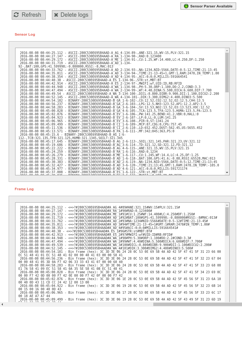
- The "Refresh" button will load again the log files.
- The "Delete logs" button will delete the files, allowing to clean some space in the device.
Sensor list
In this section, the user can view the list of available sensors in the system and add or delete user custom sensors.
By default, Meshlium recognizes all Libelium official sensors. The button "Update sensors" updates the Meshlium unit with the latest Libelium's official sensor list: Meshlium will connect to Libelium's servers and will download the latest configuration files.
All additional sensors (not officially integrated by Libelium) must be specified by the user. Users can add and remove custom sensors in an easy and simple way on the Manager System. The update process will not change the "User sensors" list.
To add a new sensor the user must complete the fields:
- ASCII ID: sensor id for ASCII frame.
- Fields: This field specifies the number of sensor fields sent in the frame. This helps to calculate the frame length.
- Type: type of fields:
- uint8_t
- int
- float
- string
- ulong
- array (ulong)
- Units: Units for the sensor added.
Once all fields are filled in, click on the button "Add sensor".
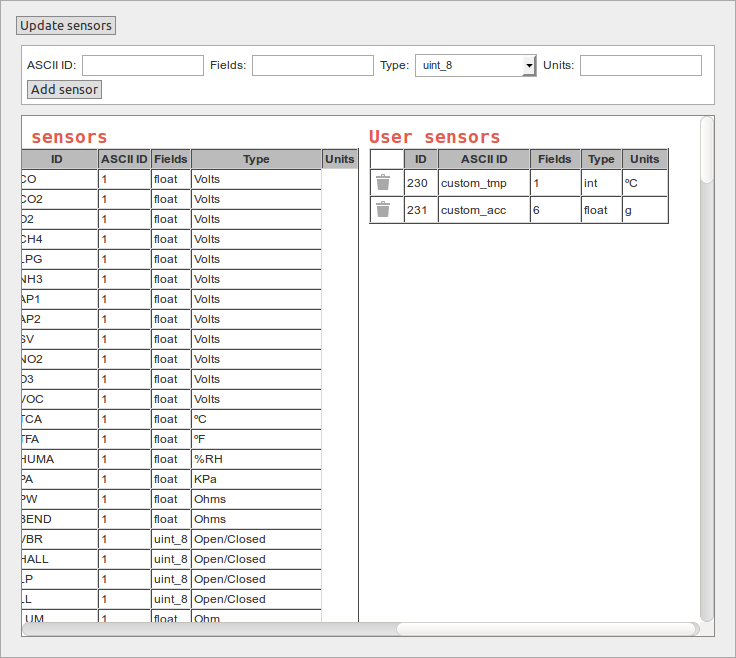
To delete sensor the user must press the garbage can that appears to the left of the description of the sensor. To complete the action should accept a confirmation message.
OTA via FTP
Meshlium can also be used as an FTP server to prepare the binary files to be downloaded by Waspmote.
For more info about Over the Air Programming go to:
https://development.libelium.com/over-the-air-programming-guide/
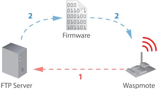
This feature allows reprogramming Waspmote using an FTP server (inside Meshlium) and FTP client (Waspmote itself).
There are two basic steps involved in OTA procedure:
- Step 1: Waspmote requests a special text file which gives information about the program to update: program name, version, size, etc.
- Step 2: If the information given is correct, Waspmote queries the FTP server for a new program binary file and it updates its flash memory in order to run the new program.
Besides, a default user is configured in Meshlium FTP Server with the following settings:
- user: ota
- password: libelium
This user directly connects to the following path in Meshlium's system directory where the application creates all the binary and UPGRADE.TXT files:
/mnt/user/ota
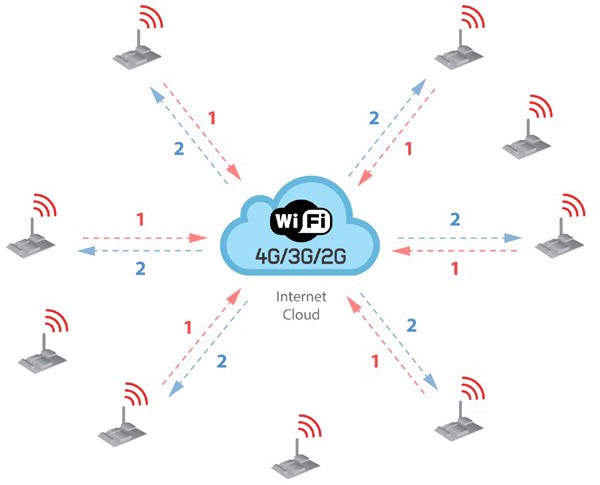
Inside "Sensor Network" there is the section OTA - FTP. Users can prepare the binary files to be downloaded by Waspmote. Then, the user can generate UPGRADE.TXT text file necessary to do OTA with 4G/3G/GPRS/GSM/WiFi via FTP.
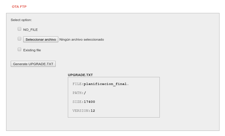
Firstly, there are three possibilities to be chosen:
- Select NO_FILE to inform Waspmote that no OTA is necessary.
- Select a new file generated by the Waspmote platform IDE so as to update the Waspmote's program.
- Select an existing binary if the user needs to update to an older program. The files are stored in the following path: /mnt/user/ota.
Select NO_FILE to inform Waspmote that no OTA is necessary.
Select a new file generated by the Waspmote platform IDE so as to update the Waspmote's program.
Select an existing binary if the user needs to update to an older program. The files are stored in the following path: /mnt/user/ota.
Secondly, the program version is always set by the user before generating the new UPGRADE.TXT file. There is a specific input to indicate the program version. It must be defined as a 1-unsigned-byte number (range: from 0 to 255).
Finally, there is a button to generate the new UPGRADE.TXT file.
Once these steps have been completed, the binary file and the proper UPGRADE.TXT file will be ready for the Waspmote devices deployed which try to perform OTA via FTP transmission. This file is shown in the window of the application representing the actual binary prepared for OTA.